• Skip to primary navigation
  • Skip to main content
  • Skip to primary sidebar
  • Skip to footer

3D CAD World

Over 50,000 3D CAD Tips & Tutorials. 3D CAD News by applications and CAD industry news.

  • 3D CAD Package Tips
    • Alibre
    • Autodesk
    • Catia
    • Creo
    • Inventor
    • Onshape
    • Pro/Engineer
    • Siemens PLM
    • SolidWorks
    • SpaceClaim
  • CAD Hardware
  • CAD Industry News
    • Company News
      • Autodesk News
      • Catia News & Events
      • PTC News
      • Siemens PLM & Events
      • SolidWorks News & Events
      • SpaceClaim News
    • Rapid Prototyping
    • Simulation Software
  • Prototype Parts
  • User Forums
    • MCAD Central
    • 3D CAD Forums
    • Engineering Exchange
  • CAD Resources
    • 3D CAD Models
  • Videos

cad

CAD and the Internet of Things

October 23, 2015 By Jean Thilmany Leave a Comment

The Internet of Things is certainly being hyped, but is it overhyped? We’ll see when the technology becomes mainstream—as business analysts say it will– within a few years’ time. The way Internet of Things (IoT) will become part of designers’ and engineers’ job also remains to be seen. But engineering software maker PTC says there’s a definite role and that PTC itself will be a part of it.

Certainly designers and engineers will be creating the sensors used for IoT as well as ensuring the machines, manufacturing and transportation—and nearly everything else–they design will be IoT ready. Transport for London, for example, the organization that runs the London Underground (pictured), recently announced it’s implementing the IoT to streamline maintenance of the system, improve customer service and boost efficiency by 30 percent over three years.800px-Lancaster_Gate_tube-618x412.

The IoT calls upon wireless sensors that continuously monitor the operation of machines of all types, no matter where they’re located, and then aggregates the data so it can be broken out and analyzed to discover trends and make conclusions that can’t be drawn from local data or from lag-time feedback.

Management consulting firm Accenture predicts the global Industrial IoT landscape (IoT for industrial use) will be worth $14.2 trillion by 2022. Technology research firm Gartner Inc. forecasts nearly 26 billion devices on the Internet of Things by 2020.

To become linked with IoT, PTC has acquired ThingWorx, an IoT platform provider and Axeda, which provides cloud-based software for managing connected machines. Earlier this month, ThingWorx announced an agreement to offer semiconductor manufacturer Analog Devices customers an integrated sensor-to-cloud environment on the platform.

James Heppelmann, PTC chief executive officer, wrote last November on the stock market analysis and insights blog Seeking Alpha that IoT will redefine what CAD and PLM are about.

The company has embraced IoT by selling its ThingWorx and Axeda offerings to users outside PTC’s regularly customer base, he said.

IoT gives PTC also an opportunity to “improve the capabilities, value proposition and differentiation of our CAD, PLM, ALM and SLM offerings,” he wrote. Application lifecycle development (ALM) software is used to manage computer software while service lifecycle management (SLM) software is used to manage the delivery of services.

“As we land these new logos, we’ll work to expand our position by introducing SLM, which is really the killer app for IoT, as well as ALM, PLM and even CAD technologies over time,” Heppelmann wrote.

In other words, PTC will offer its engineering technologies for sale to its existing IoT customers. The engineering software maker still seems uncertain how to best merge, sell, and manage IoT, CAD, and PLM.

Which perhaps is as it should be with a technology like IoT that some researchers say will become as ubiquitious as the Internet itself.

Certainly many more engineered products will include sensors in the not-to-distant future and will be connected wirelessly. Designers and IoT will learn to play well together, though how that play will look and how far in the future it will become commonplace still is still unclear. Stay tuned.

Filed Under: News Tagged With: cad, IoT, PTC

Leveraging the Value of 3D Design Data

August 18, 2014 By Barb Schmitz Leave a Comment

Software vendors spend a lot of time and money touting the value of 3D CAD software though most of the attention is paid to the actual design process. After all, this is where engineers and designers focus most of their efforts and where the innovative designs are conceived and realized through the use of 3D CAD software.

Ideas are proposed, explored, vetted, and flushed out during the important conceptual design phase. Then engineers take those evolving concepts and convert them into fully detailed geometry that will eventually be past to manufacturing.

Downstream benefits of 3D data

The use of 3D CAD software has provided tremendous benefits to the design phase of product development, but leveraging that resulting 3D design data elsewhere in the enterprise–and even outside of the corporate walls to partners and suppliers–is where a bounty of potential benefits awaits. Many companies have barely scratched the surface of realizing these downstream benefits of 3D data.

After all, it takes a village, or at least an entire enterprise, to successfully conceive, design, manufacture and get any new product to market. This somewhat Herculean effort requires the carefully coordinated efforts of multiple disciplines, which all play a critical role in the ultimate market success of any product.

While engineering and manufacturing play a starring role in the design-test-build phases of product development, other departments, such as marketing, sales, service quality, training, and technical documentation, also play heavily into the successful rollout and support of final products. These departments are often referred to as off the critical path, but their involvement is still critical.

Make it easier for non-technical users to create associative 2D and 3D product communication deliverable directly from your 3D CAD data using products, such as SolidWorks Composer shown here.
Make it easier for non-technical users to create associative 2D and 3D product communication deliverables directly from your 3D CAD data using products, such as SolidWorks Composer shown here.

Despite this, not all companies are taking advantage of leveraging CAD data to these important downstream design consumers. Let’s take a look at how downstream departments can leverage the use of 3D design data and what tasks can be done better by using it.

Better sales proposals. Create proposals that feature fully rendered 3D images and animations and you’ll get an edge on any competition still submitting bids in 2D. Creating proposals in 3D also helps potential customers understand the intricacies of your product.

Better sales tools. Help out your marketing department by providing them with 3D photorealistic renderings of products. Being able to create supporting collateral in advance using 3D CAD data enables marketers to seed the market to assess interest in a new product.

More effective training materials. Instructors can hit the ground running by tapping 3D CAD data to create the technical manuals and tutorials that will be used to help users understand how to ultimately use the product.

Assess maintenance issues. Regardless of how amazing and innovative a new product is, at some point it will be need to be serviced. Document field service procedures using 3D CAD data prior to manufacturing to access how easy or difficult it will be to service that product once built.

Create assembly instructions. Instead of manually creating assembly instructions based on cryptic 2D drawings, 3D assembly models can be quickly and easily “exploded” in 3D CAD to enable folks downstream to easily include these views of a product’s internal components in technical illustrations, assembly instructions and customer documentation.

Collaborate better. Design review teams today have expanded to include many non-technical members, including marketing and sales. Sharing a 3D model with which they can interact can help them understand how a product will function so they can add their input–without having to know how to use a 3D CAD system or interpret a 2D drawing.

The bottom line

The ability to share 3D data downstream with non-engineering departments can deliver significant bang for the buck by increasing productivity, optimizing workflows, and providing non-technical personnel with a voice in the development of new products in design reviews.

In order to realize these benefits, however, companies must educate, train and encourage these downstream design participants to use and understand the extended value of 3D CAD data and how they can use it to be more productive and better contribute to the success of future products.

Barb Schmitz

Filed Under: News Tagged With: 3D CAD, cad, composer, SolidWorks

SolidThinking Introduces Inspire 2014

August 15, 2014 By Barb Schmitz Leave a Comment

Engineers and designers are under constant pressure to design innovative products. They are also under the gun to get these new products to market faster than ever. In order to empower them to accomplish these goals, design and simulation software tools are being increasingly used to optimize products early in the conceptual phase of development, when ideas can be vetted and changes can be made easily and at less cost than late-stage design changes.

One such software tool is latest version of SolidThinking’s Inspire software, which enables users to create and investigate structurally efficient concepts quickly and easily, leading to reductions in cost, development time, material consumption, and product weight. SolidThinking Inspire is used by design engineers, product designers, and architects in multiple industries including aerospace, automotive, heavy industry, architecture, and consumer products.

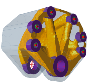
SolidThinking Inspire 2014 software enables design engineers, product designers, and architects to create and investigate structurally efficient concepts quickly and easily, leading to reductions in cost, development time, material consumption, and product weight.

New to Inspire 2014 are geometry simplification tools, linear static analysis, concentrated mass parts, and smoothing options, including the ability to export solid geometry. One focus of this release was increasing the software’s ease of use, making it easier for users to set up models for analysis to validate concepts, and improving the concept development phase.

“With solidThinking Inspire 2014 we focused on enhancing the concept development process by proposing designs that can be rapidly iterated and easily exported to the user’s preferred computer-aided design (CAD) tool,” says Andy Bartels, Program Manager for solidThinking Inspire. “We put a strong emphasis on improving the usability of the software while adding new features like geometry simplification tools for easier model setup and analysis to help users verify their concepts, all directly in the Inspire interface. These new features will allow customers to apply Inspire to a much broader set of design problems.”

To make it easier to visualize the improvements in features in Inspire 2014, the company created a series of videos, which include a tour of the user interface, a comprehensive overview of the latest features, and an overview of how the software fits into the product design process. In addition, customers may access tutorials created specifically for the solidThinking Inspire 2014 release, product demos and an interactive infographic. To watch the videos, click here.

Earlier this year, solidThinking released solidThinking Evolve 2014, which enables industrial designers to develop forms faster, using either a Windows PC or Mac. Evolve captures an initial sketch, then allows exploration of styling alternatives and the visualization of products with high quality renderings generated in real time.

The software combines both the modeling freedom of organic surfaces and the control of parametric solids with its unique ConstructionTree history feature. Evolve releases designers from the constraints of engineering-oriented CAD tools, while allowing the export of digital models required by others in the product development process.

Barb Schmitz

Filed Under: News Tagged With: cad, Direct Modeling, FEA

Tech Innovations Spurring Revival of U.S. Manufacturing

July 7, 2014 By Barb Schmitz Leave a Comment

A lot has been written in the press lately about the comeback of U.S. manufacturing. Several factors come into play here. Cost creep in China–due to rising inflation and wage expectations–means that as soon as 2015 the U.S. could be in cost parity with Chinese manufacturing.

Fears regarding IP security have also forced manufacturers to rethink offshoring strategies that once promised competitive cost advantages. Both of these trends are fueling what’s being called the “nearshoring” or “inshoring” trend, that is, companies bringing manufacturing back to the U.S.

Major companies, such as Ford, Apple, Caterpillar, and GE have moved nearly 20,00 manufacturing jobs back to the U.S. from Asia and Mexico with the last couple of years.

Another advantage of having of onshore manufacturing is that having the capability to manufacture close to where customers are located can increase customer responsiveness and decrease turnaround times, making the supply chain more predictable.

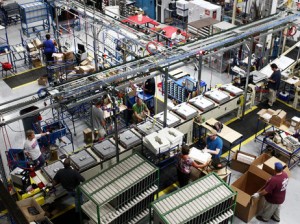
GE's Appliance Park in Louisville, KY, is being revamped, thanks to an $800 million investment in jobs, products, and manufacturing to build better, more efficient dishwashers.
GE’s Appliance Park in Louisville, KY, is being revamped, thanks to an $800 million investment in jobs, products, and manufacturing to build better, more efficient dishwashers.

Another factor contributing to an uptick in U.S. manufacturing is that the fact that natural gas prices have been reduced by two-thirds since 2008, making the U.S. more competitive for gas-intensive industries, such as petrochemicals and fertilizers.

U.S. Manufacturing Benefits from Tech Innovations

Perhaps the biggest factor, however, is the wave of technology advancements (digitization, data analytics, advanced automation, Internet of things and additive manufacturing) that are changing the landscape for U.S. manufacturers. Many of these advancements are driven by software innovations.

CAD and simulation software continue to improve manufacturers’ ability to create high-quality products faster than ever, cutting out expensive physical prototyping that in turn reduce design costs.

New additive manufacturing and 3D printing applications are making it easier for more players to become innovative manufacturers without the traditional constraints of high-volume manufacturing. Crowdsourcing and crowdfunding sites and platforms are also encouraging more would-be inventors to enter the market.

Robotics are reducing the need for labor, again reducing the cost of manufacturing products. The ability to embed sensors through the whole system, link them through the “industrial Internet,” and extract insight from the data means that U.S. companies are now leading the world in accelerating product development cycles and delivering on the promise of mass customization.

What is the result of all these innovations? According to Mark Muro, senior fellow at the Brookings Institution, it means, “The game is now being played on American terms. Software and brilliant machines are erasing U.S. cost deficits and giving it a shot at lasting production leadership,” says Muro.

Barb Schmitz

Filed Under: News Tagged With: 3D printing, cad, manufacturing, simulation, software

Siemens NX Helps University Design Better Soccer Players

June 23, 2014 By Barb Schmitz Leave a Comment

With all the excitement at full tilt with the 2014 FIFA World Cup underway in Brazil, the whole world seems to have gone soccer-crazy, with many people hitting local fields to practice their own ball-handling skills. At Graz University of Technology in Austria, that includes robots. The university is designing and building robots to be superior “soccer players.”

No water bottles required

Propelled by omnidirectional roller drives, the robots are fully autonomous and carry everything on board, from the power supply to the compressed air bottle for the kicking mechanism. The only input from the outside are the referee’s commands.

The need for well-defined, easy-to-communicate rules is critical for testing the efficacy of autonomous robots from an artificial intelligence perspective. Most of all, the test environment must provide changeable conditions that closely mirror reality. The game of soccer fulfills these conditions.

Battling for victory in the RoboCup

The RoboCup competition was established in the 1990s as a test bed for research, development and university education. Matches strictly follow FIFA rules and are played in various categories. Playing soccer, however, is not the point. The goal is to design methods for autonomous robots that can quickly make correct decisions based on their observations.

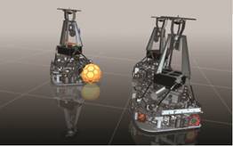
Propelled by omnidirectional roller drives, the robots are fully autonomous and carry everything on board, from the power supply to the compressed air bottle for the kicking mechanism.

For now, robots play against robots in these tournaments. However, a challenge has already been announced: In 2050, a team of robots is scheduled to play the human team holding the World Cup at the time. One team from the university has been participating in the world championship since 2003.

Tackling a new robot design required the team to improve their mechanical design process. “The older robot generations were created with a mix of 3D CAD modeling and hand drawings,” says Norbert Rath, head of mechanical engineering within the group. “This involved using a CAD system that is particularly unwieldy and forces users to employ strictly parametric methods.”

Searching for a better design tool

The CAD tool the team used in the past also had certain shortcomings in drawing conversion. Due to high application complexity, work could not commence without an enormous amount of training and familiarization.

With frequent staff changes, the team searched for an alternative that would provide high-functional capabilities, while being easy to learn with minimal training requirements, along with the ability to distribute work so that multiple team members could contribute to the overall task without requiring significant coordination efforts.

Researchers at Graz University of Technology in Austria are using Siemens NX software to design robots to be superior soccer players.

As a result, in early in 2009, the RoboCup team licensed NX software from Siemens PLM Software. Adopting the use of NX, Graz University of Technology students reported significant benefits, which included: reduced data preparation work from a week to a day; improved data efficacy; facilitated collaboration between team members; reduced number of physical prototypes; and optimized budget and resources.

To learn more about Siemens NX software, click here.

Barb Schmitz

Filed Under: News, Siemens Blogs, Siemens PLM Tagged With: artificial intelligence, cad, NX

Creo 3.0 Announced at PTC Live Global

June 17, 2014 By Barb Schmitz Leave a Comment

Amid the excitement of users, partners, analysts and members of the press–along with hundreds of Boston-based employees, PTC announces the release of Creo 3.0. Among the most impressive of its enhancements and feature upgrades is what PTC has dubbed Unite Technology.

Designed to help its customers overcome the struggles of dealing with CAD data in multiple formats, Unite Technology provides users with an easier way to use multi-CAD data in Creo. The new release also offers new integrated concept design tools that make it easy and fast to capture concept ideas–both good and bad–for future use and to reuse concept designs in the detailed design process.

Other productivity enhancements within the release will reportedly add to customers’ ability to focus on higher levels of innovation and product quality.

Unite Technology.

Unite technology enables CAD data of varying formats to be used directly in Creo apps, including Creo Parametric, Creo Direct, Creo Simulate, and Creo Options Modeler apps. This ability should go a long ways towards customers gaining efficiencies from consolidating multiple CAD systems onto PTC Creo.

The Unite Technology should also facilitate design collaboration with partners who use competing CAD tools by allowing users to easily reuse existing CAD data as is, in its current format, with no need for a costly upfront migration. It also enables users to convert existing legacy data to PTC Creo easily, on demand, and only when modifications are actually needed.

There is no need to convert entire assemblies to modify individual parts, users simply convert parts as changes are required.

Creo’s Unite Technology makes collaboration easier because it enables design participants to natively open SolidWorks, CATIA and NX files directly in PTC Creo without the need for additional software or any error-prone translation or conversion process. Users can also import SolidWorks, CATIA, NX, Solid Edge and Autodesk Inventor files into Creo without the need for additional software.

This new functionality also enables higher levels of concurrent engineering between the product development teams and suppliers/partners/customers by allowing designers to quickly and easily incorporate native CAD geometry created in other systems earlier in the process, create design intent across CAD formats and, as new versions of the non-PTC Creo data are updated in the assembly, ensure that any design intent build between the original part and the PTC Creo parts are protected when the part is updated.

Unite also helps promote the reuse and sharing of data and eliminates the need to manage many secondary formats, and significantly reduces the need to export data in neutral formats. Data can be shared in customer/supplier’s native format, eliminating the step of using neutral file formats.

The new release of Creo 3.0 will enable customers to work and consolidate data from any CAD source.

New concept design tools

PTC Creo 3.0 has also made some improvements in the area of concept design. These new tools and features include:
* Align Freestyle design functionality (part of PTC Creo Parametric) enables designers to create and drive freeform designs parametrically, combining organic geometry creation and modification with associative parametric design intent.

* Greater scalability and richer tools in PTC Creo Layout to support 2D concept engineering activities with seamless re-use in the 3D parametric environment

*A more powerful and easier-to use 3D direct modeling app (PTC Creo Direct) for quickly creating concept designs that are fully reusable in PTC Creo Parametric

* PTC Creo Design Exploration Extension provides a dedicated environment in PTC Creo Parametric for developing design alternatives, investigating modeling approaches and safely understanding the consequences of design changes.

Other new features include a completely redesigned Help system that uses Google search functionality, integrated hardware libraries, automated fastener assembly workflows, MathCAD integration (shipped free with Creo Parametric), a new 3D Thickness Check for injection-molded products, new analysis tools, photorealistic rendering courtesy of KeyShot, and improvements to the Creo Flexible Modeling Extension and ECAD Collaboration Extension.

We really just scratched the surface of all the new bells and whistles in Creo 3.0. For more information on Creo 3.0, check out this page. Creo 3.0 with Unite Technology will ship mid-July.

Barb Schmitz

Filed Under: Creo, News, PTC/CoCreate Blogs Tagged With: analysis, cad, Collaboration, multi-CAD

Design Technology Behind the Scenes at 2014 World Cup

June 12, 2014 By Barb Schmitz Leave a Comment

Every four years, national soccer–or football as the rest of the world calls it–teams from across the globe duke it out to determine the best square on the planet. An estimated one billion viewers will be glued to their seats watching the action that kicks off today in Brazil, nearly 900 million more than who tuned in for this year’s Super Bowl.

With the excitement of the 2014 FIFA World Cup in full swing, I thought this might be a good time to remind everyone of the real unsung hero behind this year’s matches: technology! Here is a sampling of some of the technology behind the scenes at this year’s World Cup.

No more bad calls. Thanks to new wearable smartwatches, referees in Rio de Janeiro won’t have to trust their own eyes on whether the ball crosses the goal line. The smartwatches used in Brazil are made by a German company called GoalControl, which installed 14 cameras that track the ball around the pitch. The watches will vibrate and display the word “GOAL” each time the ball crosses the goal line. Good news for fans still enraged over the infamous bad call made during the 2010 in London when England was denied a score in a match against Germany, even though the ball had clearly passed the goal line.

Smartwatches and 14 cameras will determine whether the ball crosses the goal line at this year's World Cup matches.
Smartwatches and 14 cameras will determine whether the ball crosses the goal line at this year’s World Cup matches.

Crowd control. With tens of thousands of excited soccer fans descending upon the Estadio Nacional Mane Garrincha stadium in Brazil, crowd safety is of utmost importance. With past tragedies in mind, the structural integrity of the facility is critical. Fortunately the stadium has been analysis validated that the fierce Brazilian winds won’t impact the safety for spectators and teams. Simulation specialists at ANSYS channel partner ESSS used ANSYS CFD software to predict airflow around the stadium and pressure on the stadium roof. The specialists also used ANSYS FEA software to study the combined effects of wind, stadium infrastructure and a traditionally rowdy crowd. Engineers completed the analysis in two weeks – about one-tenth the time required for traditional wind-tunnel validation – for 66 percent lower costs compared to physical testing methods.

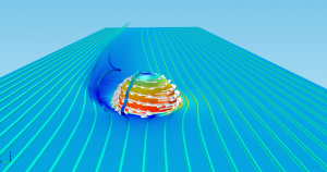
Bend it like Beckham. The curl obtained with the inside of the soccer cleat, or football boot, which was made somewhat famous by David Beckham, and the curl with the the outside of the cleat, is due to the Magnus effect. The effect, named after the scientist who first observed the effect in a lab in the 1850s, explains the side-force on a sphere that is both rotating and moving forward. Check out this blog by COMSOL to see how the company used its multi physics software to analyze the World Cup match ball.

This show the velocity and pressure fields around the rotating forward-moving ball and a rotating cylinder. The velocity at the equator is much higher on the side of the ball that rotates with the direction of the ball, as it slides the air past its surface. On the other side of the ball, its rotation and forward movement work in opposite directions.

Turf wars. Real turf fields are pretty to look at, but high-maintenance costs lead to the investigation into alternative artificial surfaces. The first attempt in 1981 in London failed miserably. The surface brought on odd bounces and an increased likelihood of injuries. In 1996 a successful hybrid grass system was introduced, featuring millions of synthetic fibers injected into natural grasses. These hybrid systems can take up to three times more wear and tear than natural grass and can be installed in as little as three weeks. A Dutch company METAL Machinebouwers used Solidworks CAD software to design the machines used in the first stage of the installation process: creating the artificial fibers that will be planted into the ground.

Filed Under: CAE, CFD, News, Simulation Software, SolidWorks Tagged With: ANSYS, cad, CFD, COMSOL, FEA, SolidWorks

ETRAGE Demonstrates a Better Way to Share Files with SubContractors

June 10, 2014 By Barb Schmitz Leave a Comment

ETRAGE LLC, a systems integration software company, will be presenting a solution that will make it easier for companies to provide access to 2D and 3D design files for their subcontractors at this year’s PTC’s Live Global Conference in Boston, June 15-17.

The presentation will describe the process of how ETRAGE customer COM DEV Ltd. now provides immediate access for its sub-contractors to 2D PDF and 3D STEP and ACIS files of design drawings and models. Options investigated include an on-demand call to the COM DEV FTP site, a customized FTP portal and the final solution of using Windchill directly through the ETRAGE Plot Service for PTC Windchill-PSW.

ENTRGE will present how to provide immediate access for sub-contractors to 2D PDF and 3D STEP and ACIS files of design drawings and models at this year's PTC Live Global Conference.
ENTRGE will present how to provide immediate access to its sub-contractors to 2D PDF and 3D STEP and ACIS files of design drawings and models at this year’s PTC Live Global Conference.

Eugene Stewart, senior Windchill administrator at COM DEV, explains how the solution was implemented. “Now vendors and customers are allowed into the COM DEV Windchill system for direct access to our latest designs. The On-Demand operating mode of PSW allows them to pull the files in a number of common formats to suit their many needs. In addition, COM DEV realizes a 40-day annual savings of a designers’ time.”

Bojan Rapaic, founder and president of ETRAGE LLC comments, “COM DEV is one of many of our clients seeing this type of a return on investment. Teams are required to be much more efficient today and ‘teams’ extend to sub-contractors. We see significant benefit to providing subcontractors with direct access to approved files.”

In addition, ETRAGE will have demonstrations of the PTC Windchill – ERP integration solutions, SharePoint Integration product, ETRAGE Bulk Loader, ETRAGE Quality Server, ETRAGE Smart PDF, ETRAGE Drawing Notes Search, ETRAGE Model Clean-up Utilities and ETRAGE Viewer.

If you’re in Boston for the PTC event, be sure and stop by the ENTRAGE booth (#506) to get a hands-on demo and to discuss your company’s specific needs.

Barb Schmitz

Filed Under: News, PLM/PDM, PTC News, PTC/CoCreate Blogs Tagged With: cad, file sharing, Windchill

IronCAD Offers Free Training to Customers and Prospects

May 30, 2014 By Barb Schmitz Leave a Comment

IronCAD, a provider of design productivity solutions, announces that its new introductory training program is now available for free to anyone evaluating IronCAD solutions. The program offers users best practices training aimed at improving the customer experience in design and collaboration by showing how to design better products, faster.

Individual components of IronCAD 2014 can be used standalone, complementary within an existing design environment, or can be used together to collaborate effectively throughout the enterprise to extend productivity.

IronCAD is now offering free evaluation and training to anyone, including existing customers and prospects.

In addition to this free introductory training, all new users will be able to take advantage of the latest customer improvements in productivity and stability that have been released as part of this program.

Users will experience increases in productivity during the design process with additional controls added in the TriBall for more precise array patterns and better interoperability with DWG including support for reference dimensions among a few of the many improvements.

“We have always recognized that our approach to design was fast and effective, and while our user interface is intuitive, it’s always best for new users to have some level of introductory training,” said Richard Serna V.P. of Sales at IronCAD. “With this training in place, anyone can get up to speed quickly and become really productive allowing them to really evaluate how the product could impact them and help to design, collaborate and freely share their ideas on a global level.”

Anyone interested in giving IronCAD a free test drive, along with free training, you can download and install the latest version of IronCAD 2014 here.

Barb Schmitz

Filed Under: 3D CAD Package Tips, CAD Package Tagged With: cad, IronCAD

Virtalis Introduces Visionary Render Immersive Design Software

March 21, 2014 By Barb Schmitz Leave a Comment

Without officially dating myself, I can say that I’ve been researching and writing about virtual reality (VR) technology since its inception. We all wrote about the exciting predictions about how the technology would revolutionize the way product designers created new products.

Imagine designing a product within that product’s environment? No interface between input device and the product model. Seemed too good to be true and it was to a large extent just that. Yes, immersive technologies have rocked the video gamer’s world, enabling players to full immerse themselves in virtual environments that are so close to reality that they can be overwhelming to some.

Back to the real (design) world, however, and the promise hasn’t quite been realized. In architecture, virtual environments have had an impact, enabling prospective home owners to do virtual walk throughs of homes long before construction is started. Or enable architects to walk through and visualize the impact of various criteria on their designs.

In product design, however, multiple ancillary technologies have split off from the broader virtual reality concept and are being renamed other terms, such as immersive design, virtual prototyping, etc.

The vision of product designers wearing 3D goggles geared up with space-age input devices and wondering through massive datasets morphed into virtual environments and manipulating or changing product models just like a sculptor would mold clay…not so much.

Visionary Render software allows users to access and experience a real-time, interactive and immersive Virtual Reality (VR) environment created from huge 3D datasets.

Virtual reality re-emerges

Because of my background in covering virtual reality, anytime news pops up covering the technology, it peaks my interest. This week I came across news of a company showcasing immersive VR software. Visionary Render allows users to access and experience a real-time, interactive and immersive VR environment created from massive 3D datasets.

Users can work alone, in small groups, or collaborate with colleagues located elsewhere in a common virtual environment to perform detailed design reviews, rehearse in-depth training tasks, validate maintenance procedures or verify assembly and manufacturing processes. The software allows importing and visualizing of million+ part CAD datasets, enabling full immersion within the VR environment.

“Visionary Render delivers VR capabilities to CAD users and benefits throughout the product lifecycle and you don’t have to be a VR expert to use it,” says Virtalis Managing Director David Cockburn-Price. “Consequently, Visionary Render allows users to easily interact with and immerse themselves in their data on a human scale, to collaborate with others in a single VR environment and to tap into the benefits that flow from those activities throughout the product lifecycle.”

Visionary Render delivers advanced rendering in real-time with ease of importing from a range of data sources, maintaining naming, hierarchies and the associated metadata. Not only that, but CAD is visualized on immersive human-scale, via collaborative VR display systems, such as the Virtalis ActiveWorks portfolio.

Key Benefits of Visionary Render:

• Interactive and immersive capability enhances communication and understanding
• Unique 3D semi-transparent User Interface reinforces the 3D
• Handle and manage huge and complex CAD data sources seamlessly
• Collaborate in a single VR environment – Globally
• Reduce load times significantly
• Cluster aware for increased performance
• Collision detection for the entire model enhances realism and improves understanding

I’m certainly intrigued and once again excited about the possible applications of a technology I’ve been watching closely for the past two decades. It’s easy to see how VR can help product designers not only design better but collaborate more effectively with others involved in design reviews, especially those without CAD expertise.

For more information on Visionary Render, check out the company’s web site. Or check out this cool video.

Barb Schmitz

Filed Under: News Tagged With: cad, immersive design, virtual reality

  • Go to page 1
  • Go to page 2
  • Go to page 3
  • Go to page 4
  • Go to Next Page »

Primary Sidebar

3D CAD NEWSLETTERS

MakePartsFast

Footer

3D CAD World logo

DESIGN WORLD NETWORK

Design World Online
The Robot Report
Coupling Tips
Motion Control Tips
Linear Motion Tips
Bearing Tips

3D CAD WORLD

  • Subscribe to our newsletter
  • Advertise with us
  • Contact us
Follow us on Twitter Add us on Facebook Add us on LinkedIn Add us on Instagram Add us on YouTube

3D CAD World - Copyright © 2022 · WTWH Media LLC and its licensors. All rights reserved.
The material on this site may not be reproduced, distributed, transmitted, cached or otherwise used, except with the prior written permission of WTWH Media.

Privacy Policy