• Skip to primary navigation
  • Skip to main content
  • Skip to primary sidebar
  • Skip to footer

3D CAD World

Over 50,000 3D CAD Tips & Tutorials. 3D CAD News by applications and CAD industry news.

  • 3D CAD Package Tips
    • Alibre
    • Autodesk
    • Catia
    • Creo
    • Inventor
    • Onshape
    • Pro/Engineer
    • Siemens PLM
    • SolidWorks
    • SpaceClaim
  • CAD Hardware
  • CAD Industry News
    • Company News
      • Autodesk News
      • Catia News & Events
      • PTC News
      • Siemens PLM & Events
      • SolidWorks News & Events
      • SpaceClaim News
    • Rapid Prototyping
    • Simulation Software
  • Prototype Parts
  • User Forums
    • MCAD Central
    • 3D CAD Forums
    • Engineering Exchange
  • CAD Resources
    • 3D CAD Models
  • Videos

Evan Yares

The failed promise of parametric CAD, final chapter: A viable solution

November 18, 2013 By Evan Yares 5 Comments

Model reuse
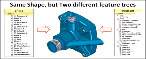
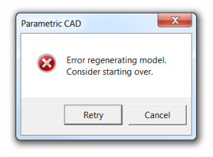
What is the failed promise of parametric CAD? In short, model reuse.

It’s a lot more difficult than it ought to be, for a variety of reasons. Several months back, I wrote a series of articles discussing those reasons, as well as some of the solutions that have come up over the years.  What was missing from the series was a final chapter; a detailed description of what could prove to be a viable solution to problems with model reuse: the resilient modeling strategy.

The resilient modeling strategy (RMS) is the brainchild of Richard “Dick” Gebhard. I wrote about Dick last June, in the article A Resilient Modeling Strategy. He’s a low-key guy with deep experience and serious expertise in the practical use of MCAD software. Over his career in CAD, he’s been a reseller for CADKEY, Pro/E, and most recently, Solid Edge.

RMS is a best practice for creating CAD models that are stable and easily reusable (even by inexperienced users.)  It can be learned and easily used by typical CAD users, it preserves design intent in models, and provides a mechanism by which managers or checkers can quickly validate a model’s quality.

Resilient Modeling Strategy

When Dick first started thinking about the concepts that make up the resilient modeling strategy, it was natural that it was in the context of showing the advantages of Synchronous Technology (The Siemens PLM brand name for its version of direct modeling.) In our discussions about RMS over the last year or so, I pointed out that, while I thought that RMS did indeed demonstrate the benefits of hybrid history/direct modeling in Solid Edge, for it to be taken seriously, and not be unfairly dismissed as a marketing initiative for Solid Edge, it needed to work with a wide variety of MCAD tools. I think Dick got where I was coming from, because he’s continued to refine and generalize RMS, with feedback from users of a number of MCAD systems.

In its current incarnation, RMS works particularly well with Solid Edge, as might be expected, but also works very well with Creo, NX, CATIA, and IronCAD (all of which are hybrid history/direct systems.) Further, with a few modifications, it can provide compelling value with SolidWorks, Inventor, and Pro/E (all of which are primarily history-oriented systems.)

It’s significant that RMS is also free to use. While Dick is available to provide presentations, seminars, and training, he has not attempted to patent, or keep as trade secrets, the underlying concepts of RMS. (He does claim a trademark on the term “Resilient Modeling Strategy,” which means that organizations offering commercial training on RMS will need to get Dick’s OK to use the term.)

Dick has posted an introductory presentation on RMS at resilientmodeling.com. While the entire presentation is 20 minutes long, the first 3-1/2 minutes cover the problems that people invariably experience when reusing or editing history-based CAD models. Watching that much will likely convince you to watch the rest.

On Wednesday, November 20, at 10:00 AM PST, Dick will be hosting a webinar on RMS. It’s scheduled to last just 30 minutes, with the emphasis on content, not hype. If you’re a serious CAD user or a CAD manager (or, for that matter, you work for an MCAD developer), it’ll be well worth your time to attend.

TL;DR: Resilient Modeling Strategy is a best practice for creating high quality reusable 3D MCAD models. It works with many CAD systems, it’s easy to learn and use, and it’s free. Big payoff for MCAD users. 

Presentation at resilientmodeling.com

Register for Nov 20 webinar on Resilient Modeling


Filed Under: Catia, Creo, Evan Yares, Featured, Inventor, News, Pro/Engineer, Siemens PLM, SolidWorks Tagged With: 3D CAD, Catia, Dassault Systemes, Evan Yares, Inventor, IronCAD, PTC, Siemens PLM, Solid Edge, SolidWorks

Leveraging 3D CAD Data

August 13, 2013 By Evan Yares Leave a Comment

by Evan Yares, Senior Editor

In the 2013 State of 3D Collaboration and Interoperability Report, published last May, Chad Jackson, Principal Analyst at Lifecycle Insights, asked the question, “Have we finally realized the vision of fully leveraging the 3D model?”

In the survey on which the report was based, respondents were asked about their use of 3D, both on the critical path (within engineering and manufacturing), and off the critical path (in service, quality, training, technical docs, marketing, sales, and other areas.) The results show that the use of 3D on the critical path is stronger than its use off the critical path. Though the use of 3D in downstream processes is growing, it’s pretty clear that relatively few companies are even close to fully leveraging their 3D CAD models.

3d-models-on-off-critcal-path
When it comes to leveraging the 3D model, the use of this software for critical path applications, like engineering and manufacturing (top), is stronger than with off-the-critical-path applications (bottom), such as training documentation, marketing, sales, and service literature or applications.

To understand why industry is where it is with respect to the use of 3D, it might help to step back a bit, into the history of CAD.

While 3D CAD systems have been around nearly as long as 2D, for the first 25 years of the CAD era, 2D was dominant. It wasn’t until late 1980s, with the introduction of Pro/ENGINEER—the first commercially successful parametric solid modeling CAD system—that 3D really came into its own.

With Pro/E, designers could first create 3D models, then quickly and easily create associative 2D drawings. When they modified the 3D models, the 2D drawings were automatically updated. Pro/E provided the benefits of 3D, without forcing its users to abandon their long entrenched 2D drawing centric product development processes.

Pro/E was incredibly influential, and most competitive CAD systems (with the exception of those designed primarily for aesthetic surface design) adopted a similar approach, coupling feature-based 3D solid modeling with associative 2D drawing creation and annotation.

Throughout the 1990s, it was pretty common for designers to use 3D model data in downstream processes. Yet, it was not convenient, requiring use of 3D models, as well as annotation information from drawings.

As 3D CAD systems matured, their developers started including model annotation tools, so designers could add information needed for manufacturing (such as dimensions, tolerances, assembly notes, and so on) directly to 3D models. CATIA, Unigraphics, I-DES, and Pro/E each had their own proprietary tools of this type. The problem was that they all worked differently, and weren’t compatible with each other. With no recognized standard methods for creating model annotations, most companies continued to use 2D drawings for conveying and maintaining manufacturing information.

In 1997, driven largely by the aerospace and defense industry and the DoD, ASME started work on what would become the Y14.41-2003 standard for Digital Product Definition Data Practices. The objective of the standard was to support the use of either model plus drawing, or model alone, as a complete product specification. Y14.41 was the first of a group of standards that collectively defined what has become known as product and manufacturing information (PMI).

Today, there are at least five different ways that companies can use CAD:

  1. 2D drawing as authority (full definition in drawing, no 3D model)
  2. 2.2D drawing as authority + 3D model (full definition in drawing, model not distributed)
  3. 3.2D drawing + 3D model together as authority (partial definition in both)
  4. 4.2D drawing as authority + 3D model as authority (full definition in model, either full or partial definition in drawing, automatically generated from model)
  5. 5.3D model as authority (full definition in model, no 2D drawing)

The first classification here represents traditional 2D computer-aided drafting. The second represents the lowest level of 3D CAD. The third classification is the most common way datasets are structured in many mainstream manufacturing applications today. The fourth and fifth classifications represent how datasets are structured in organizations pursuing model-based definition (MBD) initiatives—particularly in aerospace enterprises.

2d-authority-model
A 2D authority model, fully defined

MBD
Model-based definition is one of a number of “model-based” initiatives, all of which have as their foundation the concept of using semantically rich models to represent the functional characteristics of a product. (Among the list of interesting model-based initiatives are model-based development and model-based design, both of which share the MBD acronym with model-based definition, but neither of which are related to model-based definition. They are initiatives related to the design of complex software systems and control systems, respectively.)

The concept of MBD grew out of a big vision concept called model-based engineering, and was itself, at one time, a very big vision concept. Fortunately, sane minds prevailed, and people involved with the MBD initiative focused their energies on making it pragmatic rather than aspirational. They focused on smartening-up 3D model data, to enable downstream usability. An MBD product model is not hard to understand:

It’s a combination of 3D geometry and PMI (including explicitly defined dimensions, tolerances, notes, GD&T, welding symbols, surface texture symbols, and associated data.)

3d-authority-model
A 3D authority model, fully defined using PMI

The PMI is semantic (readable by either humans, or computer programs), associative to the 3D geometry, and standards-based. Any number of views of the model can be composed, detailed, and annotated for specific downstream operations.

While MBD is often thought of as mostly being about “getting rid of drawings,” it’s really more about getting rid of the need to use drawings for things they’re not good for. In an MBD context, it’s still possible to create drawings in the traditional way, but MBD offers a better way: it’s exceptionally easy to create drawings that are 2D projections of the views included in the product model. These are generally simpler than traditional drawings, but they have the benefit of being 100% consistent with the model. There is never a question of which document is correct—the drawing or the model.

The process of implementing MBD in an organization starts with one important first step: Getting CAD software that supports PMI. Unfortunately, this first step also introduces one of the issues that’s held the acceptance of MBD back: lack of compatibility. While CATIA, NX, Creo, Solid Edge, SpaceClaim, and SolidWorks all support PMI, they do so in varying and inconsistent ways. And they each use proprietary data formats.

While it’s possible to get past many of the problems with the various implementations of PMI (often by the use of third party software), the experience of implementing MBD is going to be heavily flavored by the CAD vendor whose software you use. Probably.

STEP AP242
When the first standards development was done for PMI, an important piece was missing. Though ASME and ISO standards defined PMI, there was no neutral CAD file format that was capable of representing that information. Rather soon, however, the STEP AP203 format was updated to the “E2” version, which included support for PMI data. But, the support didn’t quite cross the threshold of “good enough.”

STEP-AP242-file-standard
The STEP AP242 neutral file standard will fully support PMI, as well as a diverse number of geometric representations.

Soon—likely in January—ISO will publish the STEP AP242 standard. AP242 is designed for long-term archiving of CAD data—which means that it will certainly get substantial support from CAD vendors. AP242 is also designed to provide close to full support for PMI. (There’s no such thing as absolutely complete support. There are always details that slop through the cracks.)

STEP AP242 may be good enough at representing both PMI data and 3D geometry that it becomes widely used as a primary file format in MBD initiatives on that basis alone. But what makes AP242 really interesting is a separate development, from several years ago: Direct editing CAD.

Historically, CAD systems have been great at editing their native files, and terrible at editing non-native files. Yet, to a direct editing CAD program, a STEP AP242 file is, for all practical purposes, a native file.

3DPDF
Over the last couple of years, with the support of the nonprofit 3DPDF Consortium, the 3DPDF file format has made great strides as a visual communication format for 3D CAD and MBD data.

Earlier this year, the US government updated MIL-STD-31000A, Technical Data Packages, to make it 3D MBD friendly. The new revision has a strong preference that physical product data provided to the government be defined and transmitted as 3D authority datasets. Interestingly, 3D PDF seems to hit a sweet spot, combining openness (PDF is an ISO standard), with the ability to accurately represent both 3D model data and PMI.

To date, 3DPDF has seen the most use in applications that involve human viewing. But the PRC 3D format (the preferred 3D representation for 3DPDF) includes an exact representation, which can be read and converted into NURBS curves by other applications (for example, SpaceClaim). Over time, it probably won’t be surprising if 3D PDF is used as an alternative to more traditional interoperability file formats, such as STEP.

Leveraging 3D
Bryan Fisher, of MBD360, one of the best known consultants in the area of MBD, feels that the time is right for leveraging 3D models. “Standards supporting PMI have been, and continue to be, actively developed. But, even though more work needs to be done, we’re well past the threshold of ‘good enough.’” Fisher stated. “Organizations of all sizes, in a variety of industries, have demonstrated significant cost reductions by implementing 3D model-based business processes.”

With the payoff being proven, and all the bits and pieces coming together to make the process of implementing MBD both less difficult, and less risky, we may actually be getting closer to realizing the vision of fully leveraging 3D models.

Lifecycle Insights
www.lifecycleinsights.com

Model-Based Enterprise
www.model-based-enterprise.org

STEP AP242
www.ap242.org

3DPDF Consortium
www.3dpdfconsortium.org

MBD360
www.mbd360.com

Reprint Info >>

Filed Under: CAD Blogs, Design World, General Blogs

A note about some 3D CAD changes

July 31, 2013 By Evan Yares Leave a Comment

evan-yaresSenior Editor, Evan Yares, will be leaving WTWH Media in the near future to help start up the U.S. operation of Nanosoft, a Russian company. Nanosoft’s products include nanoCAD, a so-called “freemium” 2D CAD product that is free for end users, with a subscription option for premium features and technical support.

Evan has been a wonderful contributor to Design World, both in print and online (especially on this site), with his keen insights on all things CAD. He has been a user, reseller, developer, consultant, analyst, and now editor. We wish him well in his new endeavor, and you should know that you’ll continue to see his expert analysis and opinions here on 3D CAD World from time to time.

Our coverage of this ever-changing and constantly evolving industry won’t change; we’ll still be reporting on developments, events, new products and the technology. We’re also interested in hearing from you. We’re looking for contributors and guest bloggers on this exciting technology. Please contact me at pheney@wtwhmedia.com if you’re interested in writing for us.

Filed Under: Featured

The Design World dynamic design challenge

July 31, 2013 By Evan Yares Leave a Comment

Win a free dynamic design analysis of your mechanism. Get to market faster. Be a hero to your customers.

When NASA’s JPL landed the Curiosity Rover on Mars, I was impressed. Not just that they’d done it blind (because of the time-delay in communications from Mars), but also that they’d done it by dropping the rover on cables from a rocket-powered sky crane as it descended to the surface.

Think about that for a moment: That would be hard enough to do on Earth, where they’d be able to do full-scale physical testing of prototypes. Doing it on Mars, where the gravity is different from Earth, and where they had only one shot to get it right, took some serious engineering.

My first guess about how they did it was one word: Adams. And, it turns out, I was right. Adams, from MSC software, is possibly the best known multibody dynamics simulation software system, and JPL used it to simulate the process of dropping the rover onto the surface of Mars.

Cable 1

While I’ve known about Adams for years, I’ve generally not paid all that much attention to it, because it’s often used by rocket scientists and advanced dynamicists, not design engineers. It takes a lot of expertise to setup right, and just isn’t the kind of tool that the kind of people who I hang out with would typically feel comfortable using. (OK–I admit that I know a few people who actually are rocket scientists, one of whom uses Adams, but I think you get my point.)

Last year, MSC Software released a special version of Adams (called Adams/Machinery) that was designed for my kind of people. I wouldn’t have been surprised had MSC dumbed-down Adams to make it easier to use, but they did something very different: They developed a series of wizards, that could be used to design and analyze common machine subsystems, such as gears, belts, pulleys, chains, sprockets, bearings, and cables.

Flexible Gearbox

While Adams has long been able to design and analyze these sort of subsystems, the process has required a lot of expertise and work. That’s changed. The wizards in Adams/Machinery not only make the process easier, but they also allow the designer to adjust the level of fidelity of simulation, based on their needs.

Adams/Machinery can help designers solve some otherwise tough problems:

  • Analyze bearing contact force, and predict service life,
  • Predict load and performance of power transmission systems,
  • Predict how gear ratio, friction and backlash impact the overall system performance, like the output torque or the system vibration,
  • Analyze how the contact force between gears could change due to backlash effect,
  • Study how different gear parameters impact the stress distribution of the input shaft,
  • Predict how Bearing clearance affects the gear mesh,
  • Calculate the dynamic loading of the gear, bearing, shaft or any component in the system,
  • Calculate dynamic belt tension and how slippage would affect system performance,
  • And quite a lot more.

Not too long ago, I attended MSC’s 50th anniversary user conference. While there, I got to talking with Leslie Bodnar, MSC’s marketing director, about Adams/Machinery. It occurred to me that many of the engineers who read Design World magazine are involved in designing machinery that incorporates the kind of subsystems for which Adams/Machinery is optimized. It also occurred to me that many of those engineers never do multibody dynamics analysis, because they assume the process is too hard, or too time consuming. Or, perhaps, they might not even know it’s possible.

Serpentine Belt

I had an idea: What if, instead of using boring sample problems to demonstrate the capabilities of Adams/Machinery, MSC was to run an analysis on a really interesting real world problem, from one of our readers? It’s one thing for an engineering software vendor to brag about how good their software is, but it’s another thing entirely to step up and prove it on an actual customer problem.

So, I made Leslie a proposal: Design World would hold a contest with MSC, and ask our readers to submit real-world machine design dynamics problems. We would choose a really interesting one, and MSC would work side-by-side with that reader, to run a full Adams/Machinery analysis on the problem.

For the reader, the “prize” of winning the contest would be an analysis that could help solve a sticky design problem, and get their project done and shipped faster. For MSC, it would be a chance to “put-up or shut-up, ” by showing that not only is their software up to the task of running the analysis, but also that it’s easy enough for a mere mortal (as opposed to a PhD analyst) to learn to use. This wouldn’t be some simplistic sales demo: It would be a intimate customer engagement, where they’d need to deliver a real solution. Surprisingly, she said yes, she would do it.

So, I present to you the Design World Dynamic Design Challenge, sponsored by MSC Software. Choose your stickiest dynamic design challenge (it should include cables, bearings, gears, belts, sprockets, or chains), and visit the contest registration page. There, you can register, and tell us about your design problem. You can even upload pictures or videos. If we choose your problem as the winner, MSC will work with you to nail that problem to the wall, but good.

You might wonder: Will it be worth it?  Is entering this challenge, just to have a chance to win an analysis of your mechanism, really worth the effort? You might ask the folks at JPL. Multibody dynamic analysis has paid off pretty well for them.


Filed Under: CAE, Design World, Evan Yares, Featured, Simulation Software Tagged With: Adams, MSC

The failed promise of parametric CAD part 5: A resilient modeling strategy

June 25, 2013 By Evan Yares 3 Comments

bamboo-garden
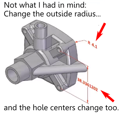
The model brittleness problem inherent with parametric feature-based modeling is a really big deal. And it’s something, honestly, that I don’t have a great answer for. I’ve even asked a few power users who I know, and their answers seemed to involve a bit of hand-waving, and a reference to having lots of experience.

While best practices are a potentially good step forward, they need to be straightforward enough that mere mortals (as opposed to power users) can follow them.

Around Christmas last year, I got a call from Richard Gebhard, an engineer’s engineer, who has made his living selling CAD, and training people to use it (including more than his fair share of power users), for longer than he would like me to admit. (I’m pretty sure I’ve been in the CAD industry longer than him, though.) Richard told me he had something he wanted to show me, and if I’d take the time to meet him, he’d buy me lunch.

What Richard showed me was a way of creating and structuring CAD models that made a lot of sense. It not only reduced parent-child dependencies, but it made them more predictable. And, more importantly, it made it a lot easier for a mere mortals to scan through the feature tree, and see if there were any grues (it’s a technical term. Feel free to look it up.)

Over the next several months, we had lunch several times. I made suggestions. He rejected some, accepted some, and thought about others. At the same time, he was bouncing his ideas off several of his best power users (including his son). By a couple of months ago, he had refined his system to the place where it would work impressively well with nearly any parametric feature-based CAD system. So, he went to work finalizing his presentation.

I had mentioned that Delphi, by patenting some of the elements of horizontal modeling, limited the number of people who could benefit from it. (Worse for them, they patented it, then filed bankruptcy. That didn’t help much.) Richard’s goal wasn’t to monetize his process. His goal was to evangelize it. To help CAD users—both power users and mere mortals—to get their jobs done better.

Richard and I had talked, over time, about what he should call this process. At first, I liked the word “robust.” In computer science, it is the ability of a system to cope with errors during execution. In economics, it is the ability of a model to remain valid under different assumptions, parameters and initial conditions. Those are good connotations. But, then I thought of one of my favorite examples of robustness. The first time I visited Russia, I noticed that the apartment buildings were built of thick poured concrete. Very robust. And nearly impossible to remodel.

Richard’s system wasn’t robust. It was resilient. So, he has named it the Resilient Modeling Strategy. RMS.

So far, I’ve written over 2,600 words, to provide some background on the problems of parametric modeling, and some of the solutions that have been offered over the years. But, after all that, I’m not going to tell you anything more about RMS. At least, not yet.

Tomorrow, Wednesday, June 26, Richard will present RMS for the first time ever, at Solid Edge University, in Cincinnati, Ohio. His presentation will start at 9:00AM local time, and will be in room 6 of the convention center. If you’re there, put it on your calendar. If not, you’ll need to wait until Richard gets back to Phoenix, and I publish a follow-up post.

RMS is not anything difficult, or fundamentally new. It’s just an elegant distillation of best practices, designed to work with nearly any parametric CAD system, and simple enough that it doesn’t get in the way.  It’ll help you make better CAD models faster.

Filed Under: Alibre, Autodesk, Creo, Design World, Evan Yares, Featured, Inventor, Pro/Engineer, Siemens PLM, SolidWorks Tagged With: Creo, Inventor, IronCAD, Solid Edge, SolidWorks

The failed promise of parametric CAD part 4: Going horizontal

June 25, 2013 By Evan Yares 12 Comments

In the early 90s, Ron Andrews, a senior product designer at Dephi’s Saginaw Steering Systems Division, became fed-up with the difficulties of editing parametric CAD models. So, he and a team of his colleagues, including Pravin Khurana, Kevin Marseilles, and Diane Landers, took on a challenge of trying to find a solution.

They came up with an interesting concept that they called horizontal modeling. Here’s a description of it from their patent abstract:

“Disclosed is a horizontal structure method of CAD/CAM manufacturing where a base feature is provided and one or more form features added to it to form a model. The form features are added in an associative relationship with the base feature, preferable a parent child relationship, but are added in a way as to have substantially no associative relationships with each other. The result is a horizontally-structured Master Process Model where any one form feature can be altered or deleted without affecting the rest of the model. Extracts are then made of the Master Process Model to show the construction of the model feature by feature over time. These extracts are then used to generate manufacturing instructions that are used to machine a real-world part from a blank shaped like the base feature.”

Here’s a picture that makes it clearer:

Horizontal Modeling

The simplest explanation I can give for it is this: You create a base feature, and bunch of datum (working) planes. You attach all the child features to those datum planes. Viola: no parent-child problems.

I admit that I’m not going to do justice to horizontal modeling in this conversation. There’s actually quite a bit to it, and it makes a lot of sense when coupled with computer-aided process planning (CAPP.)

Horizontal modeling has a handful of problems. First, it does a pretty good job of killing the possibility of having design intent expressed in the feature tree. Next, it works better with some CAD systems than others. (When horizontal modeling was in the news, SolidWorks had a problem managing the normals on datum planes, so it didn’t work too well.) The deadliest problem is that Delphi got a bunch of patents on the process, then licensed it to some training companies. From what I can see (and I may be wrong), none of these training centers offer horizontal modeling classes any more.

While, technically, you can’t use horizontal modeling without a patent license from Delphi, the concepts at its core are fairly similar to things that CAD users have been doing for years. A few years ago, Josh Mings posted on a couple of online forums that “Horizontal Modeling is just one word for it, you may also know it as Skeleton Modeling, Tier modeling, Sketch Assembly modeling, CAD
Neutral Modeling, or Body Modeling.” (It’s actually two words for it, but I get his point.)

Horizontal modeling is not a silver bullet solution for the problems inherent in parametric feature-based CAD. It’s just a best practice—a strategy for getting around the problems. It seems to be headed in the right direction, but it suffers from the complexity that comes from trying to fix too many problems at once.

Next: A Resilient Modeling Strategy

Filed Under: Alibre, Autodesk, Creo, Design World, Evan Yares, Featured, Inventor, Pro/Engineer, Siemens PLM, SolidWorks Tagged With: Creo, Inventor, IronCAD, Solid Edge, SolidWorks

The failed promise of parametric CAD part 3: The direct solution

June 25, 2013 By Evan Yares 5 Comments

Pull-PushDirect modeling—a syncretic melding of concepts pioneered by CoCreate, Trispectives, Kubotek (and many others)–has shown the most promise to cure the parametric curse.

Direct modeling is today’s hot CAD technology. PTC, Autodesk, Siemens PLM, Dassault (CATIA, but not so much SolidWorks), IronCAD, Kubotek, Bricsys, SpaceClaim (and certainly some other companies I’ve forgotten) all have their own unique implementations of it.

The common thread in direct modeling is to use standard construction techniques when modeling, and feature inferencing (or recognition) when editing. It’s easier said than done. It’s taken about 35 years of industry research to get to the place we are today—where you can click on a face of a model, and the system will recognize that you’re pointing to a feature that has some semantic value. And that’s not even considering the tremendous amount of work that has been required by legions of PhD mathematicians to develop the math that lets you push or pull on a model face, and have the system actually edit the geometry it in a useful manner.

For the CAD software, figuring out which way to edit a selection is almost a mind reading trick: A user clicks and drags on a part of a model. What would they like to happen? In some cases it’s easy: Drag once face of a rectangular block, and the system will just make it longer or shorter. But if the block is full of holes, bosses, and blends, it becomes a lot more complicated. What should the system do if you drag a face so far back that it consumes another feature, and then pull it back to where it was? Should the consumed feature be lost forever, or should the system remember it in some way, so it can be restored?

There are no right answers. It seems that no two direct modeling systems handle the decision of what is a “sensible” edit in the same way.

While direct modeling absolutely solves the model brittleness problem inherent with parametrics, it does it by simply not using parametrics. Even with hybrid parametric/direct CAD systems, the answer to the parametric curse is still to not use parametrics when you don’t need to.

The solution of “use direct modeling when you can, and learn to live with parametric hassles when you can’t” just isn’t very satisfying to me.

Next: Going horizontal

Filed Under: Alibre, Autodesk, Creo, Design World, Evan Yares, Featured, Inventor, Pro/Engineer, Siemens PLM, SolidWorks Tagged With: Creo, Inventor, IronCAD, Solid Edge, SolidWorks

The failed promise of parametric CAD part 2: The problem is editing

June 25, 2013 By Evan Yares 4 Comments

ErasermIn the previous post, I wrote about the failed promise of parametric CAD: problems such as parent-child dependencies and unwanted feature interactions, coupled with no easy way to either prevent, or check for them.

The difference between modeling and editing in a parametric CAD system is simply the difference between creating things from scratch, and modifying things you’ve already created. The distinction may seem academic, but it is only when editing that parent-child dependencies are a potential problem.

Consider a scenario, of creating a parametric part—one that you’ve worked out in your head pretty well ahead of time—where you start from scratch, modeling sequentially, and spending all your time working on the most recent feature without needing to go back to edit upstream features.

In that context, the model’s parent-child dependencies would exist, but would be benign. They’d never get in your way. That is, until you went back to edit the part.

In most cases, people don’t build models from scratch without periodically going back to adjust earlier features from time to time. In that process, they’ll catch, and be able to deal with, some of the dependencies. But not likely all, or even most, of them.

I’ve heard experienced CAD people use an interesting term for models with hidden and untested parent-child dependencies: Parts from hell. When you’re trying to modify them, you never know when a small change might cause them to completely fall apart. I think a better, more descriptive, term is brittle: Hard, but liable to break or shatter easily.

This also suggests a descriptive term for CAD models which are not liable to break or shatter easily: resilient.

I’ve only ever seen one group of users who could consistently create complex yet resilient parametric parts models from scratch: PTC application engineers from the early to mid-1990s. Of course, they could only do it during customer benchmarks, with parts they’d practiced ahead of time, where they had worked-out and memorized all the steps, and where they had a good idea of the parameter ranges. Even then, if you were to ask them to change a dimension that would cause a topological change, the models might unceremoniously blow up.

Not to paint too bleak a picture, there are certainly CAD power users who have the skills to create resilient CAD models. I’ve met more than a few of them: true professionals, who by combining experience, insight, and education, have earned the respect of their peers. They understand how to structure CAD models to avoid any problems with brittleness.

Nah. I’m just messing with you. Power users struggle with this just like us mere mortals. It’s just that their models don’t usually fall apart until you go outside the scope of parametric changes they had anticipated. Give power user’s carefully crafted CAD model to a user who has a black thumb (I’m sure someone comes to mind), and they’ll find ways to blow it up that the power user never imagined.

Next: The direct solution

Filed Under: Autodesk, Creo, Design World, Evan Yares, Featured, Inventor, Pro/Engineer, Siemens PLM, SolidWorks Tagged With: Creo, Inventor, IronCAD, Solid Edge, SolidWorks

The failed promise of parametric CAD part 1: From the beginning

June 25, 2013 By Evan Yares 28 Comments

The modern era of 3D CAD was born in September 1987, when Deere & Company bought the first two seats of Pro/Engineer, from the still new Parametric Technology Corporation. A couple of years later, Deere’s Jack Wiley was quoted in the Anderson Report, saying:

“Pro/ENGINEER is the best example I have seen to date of how solid modelers ought to work. The strength of the product is its mechanical features coupled with dimensional adjustability. The benefit of this combination is a much friendlier user interface plus an intelligent geometric database.”

According to Sam Geisberg, the founder of PTC:

“The goal is to create a system that would be flexible enough to encourage the engineer to easily consider a variety of designs. And the cost of making design changes ought to be as close to zero as possible. In addition, the traditional CAD/CAM software of the time unrealistically restricted low-cost changes to only the very front end of the design-engineering process.”

To say Pro/E was a success would be a terrible understatement. Within a few years PTC was winning major accounts from the old-line competitors. In 1992, on the strength of its product, PTC walked away with a 2,000 seat order from Caterpillar that Unigraphics had thought was in the bag.

The secret to Pro/E’s success was its parametric feature-based solid modeling approach to building 3D models. To companies such as Deere and Caterpillar, it offered a compelling vision. Imagine being able to build a virtual CAD model of an engine, and, by changing a few parameters, being able to alter its displacement, or even its number of cylinders. And even if that wasn’t achievable, it would be a great leap forward to just be able to rapidly create and explore design alternatives for parts and assemblies.

Yet, things were not that easy. In 1990, Steve Wolfe, one of the CAD industry’s most insightful observers, pointed out that Pro/E was incapable of making some seemingly simple parametric changes.

Pro/Engineer placed limits on the range of parameters. (A designer could not increase the dimension of L2 to point that L3 vanished.)

David Weisberg, editor of the Engineering Automation Report (and from whose book, The Engineering Design Revolution, I have liberally cribbed for this article), pointed out the fundamental problem with parametrics:

“The problem with a pure parametric design technique that is based upon regenerating the model from its history tree is that, as geometry is added, it is dependent upon geometry created earlier. This methodology has been described as a parent/child relationship, except that it can be many levels deep. If a parent level element is deleted or changed in certain ways it can have unexpected effects on child-level elements. In extreme cases (and sometimes in cases that were not particularly that extreme), the user was forced to totally recreate the model… Some people described designing with Pro/ENGINEER to be more similar to programming than to conventional engineering design.”

Weisberg barely scratches the surface of the issues that can create problems.

In 1991, Dr. Jami Shah wrote an Assessment of Features Technology, for Computer-Aided Design, a journal targeted to people doing research in the field of CAD. He identified that there were problems with features:

“There are no universally applicable methods for checking the validity of features. It is up to the person defining a feature to specify what is valid or invalid for a given feature. Typical checks that need to be done are: compatibility of parent/dependent features, limits on dimension, and inadvertent interference with other features. In a study for CAM-I, Shah et al. enumerated the following types of feature interactions:

  • interaction that makes a feature nonfunctional,
  • non-generic feature(s) obtained from two or more generic ones,
  • feature parameters rendered obsolete,
  • nonstandard topology,
  • feature deleted by subtraction of larger feature,
  • feature deleted by addition of larger feature.
  • open feature becomes closed,
  • inadvertent interactions from modifications.”

The important thing to notice here is that, not only are there multiple failure modes for features, there are also no universal methods for validating features. It’s left up to the user to figure out. And that process, as Weisberg hinted, is much too difficult.

Rebuild Error

Since the early days of Pro/E, a lot of work has been done, both by PTC and other companies in the CAD industry, to improve the reliability and usability of parametric feature-based CAD software. Yet, the problems that Weisberg and Shah identified still exist, and still get in the way of users being able to get the most from their software.

Next: The problem is editing.


Filed Under: 3D CAD Package Tips, Autodesk, Creo, Design World, Evan Yares, Featured, Inventor, Pro/Engineer, Siemens PLM, SolidWorks Tagged With: Creo, Inventor, IronCAD, Solid Edge, SolidWorks

Maybe you don’t need to spend an arm and a leg on CAD/CAM tools

June 6, 2013 By Evan Yares Leave a Comment

stand_multipleMy friend Rachael Dalton-Taggart, Director of Marketing Communications at Geomagic Solutions (which is now part of 3D Systems), often has interesting perspectives on the engineering software market. Every once in a while, she’ll start an email thread on some intriguing or irritating issue, and include a bunch of industry editors/anaysts/consultants in the distribution list (we all know each other, from attending shows and conferences over the years.) These email threads end up being rather like a “sitting by the pool at COFES” conversation, where we get to rant a bit, knowing that the people who are listening actually have the background to get what we’re saying.

Yesterday, Rachael dropped me an email, about an application story she’d gotten from Mecsoft. Here’s what she said (with my short comments interspersed in [square brackets]):

“I’m not sure if you would even be interested in this customer case study but I got this from MecSoft, about use of Geomagic Design [formerly Alibre Design] with ‘Alibre CAM.’ It’s a nice story. What intrigues me is that after the last ten years of people like you, me, Martyn [mutual friend of Rachael and myself, industry gadfly, and founder of Develop3D] etc discussing how ‘everyone’ already has cad, there are times when that is obviously not the case and this is one.

The more I dig into manufacturing operations, the more I see some realities that are seldom talked about: People coming here [to Geomagic] for training in inspection software who can barely turn on a computer. (Yes, they use a ruler and calipers to inspect their products.)  Companies still on 2D CAD – exclusively. We have been spoiled with the ‘top end’ stories such as Boeing, Ford and the like who spend millions on interop and enterprise-wide CAD.

Is she ever right. I spend a lot of my time looking at top-end applications, often working my tail off to understand the nuances of their technology. Yet, innumerable companies (much less, individual engineers and designers) are nowhere near being able to afford these tools. For them, moving from using a 2D CAD program such as AutoCAD LT to a relatively inexpensive 3D MCAD program such as Alibre (which was not-too-long-ago acquired by 3D Systems, and rechristened “Geomagic Design”) can be a really big deal.

Though I try to cover a broad spectrum of engineering software tools, I get more personal satisfaction out of talking about tools that empower individual engineers and designers than I do talking about tools that empower enterprises.

So, thank you, Rachael. You’re right—this is a nice story. And thank you, Mecsoft, for recognizing that simple CAD/CAM tools that don’t cost an arm and a leg can make a big difference for small businesses.

Here is the case study, written by Tim Strifler of Mecsoft, telling how one of their customers used Geomagic Design and Alibre CAM to transform his business. Again, I’ve interspersed my comments in [square brackets]:


Alibre CAM: Changing Businesses, One Shop at a Time

By Tim Strifler, Marketing Coordinator, Mecsoft

Not to toot our own horn, but we hear success stories all the time about how our customers have utilized our software in effective ways and how it’s helped their businesses. But our benchmark for a truly satisfied customer changed after speaking to Chris Milligan of CRM Fabrication & Repair. Chris began to tell us how our software has “literally changed his business” and that Alibre CAM has “brought his manufacturing capacity into the 21st century.” Let’s back up and see what lead to Chris’ success with MecSoft CAM software.

CRM Fabrication & Repair is a small family-owned fabrication and machine shop located in the hills of Northeast Georgia. Chris told us their story is one of humble beginnings and hard work. He started the company in Longview, Texas, with only a stick welder and a 1978 Ford truck. Their drawings were constructed on graph paper or on the floor with soapstone. Eventually they were able to get their hands on a student copy of AutoCAD 2D. At that time, their services were limited to what could be welded with a DC stick or TIG welding machine, or items that could be brazed with an acetylene torch rig. Fast-forward through 15 years and a relocation to Georgia, CRM Fabrication & Repair now has four full time employees, upgraded equipment and machinery, and a full machine shop. This includes a recently purchased CNC machining center and a vertical machining center.

[I think we all know people like this, who start with basic tools and raw talent, and build it into a solid business, with rabidly loyal customers. One of my favorite examples is Industrial Chassis, in Phoenix. They’re fabricators at heart, and use Alibre to design everything from fixtures, to stamping dies, to metal forming machinery.]

CRM Fabrication & Repair, of course, has also purchased a seat of both Geomagic Design (formerly Alibre Design) and Alibre CAM 3, which, in the words of Chris, has “transformed their business.”

Wheel Finishing Stand

stand_inuse4m
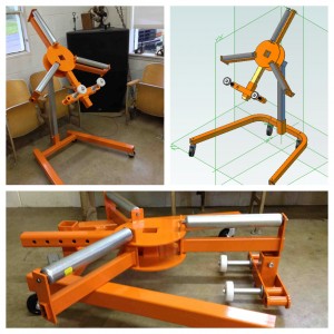
Over 10 years ago a company approached CRM Fabrication & Repair with a unique product request. The company specialized in refinishing car wheels, and they wanted a stand that would assist in this process. Of course this was before CRM Fabrication had embraced CNC and CAD/CAM software, so creating a unique product was a little more difficult. They were able to complete the product and ship the order, but it wasn’t pretty, and it wasn’t done efficiently. It was bittersweet when the customer would come back year after year and order more.

Chris was happy to have satisfied the customer’s needs, but hated producing them. “I never had the software to build them right or build them profitably.” Still, word got around to other auto shops about these handy wheel stands, and Chris received more and more orders.

He eventually had the right software (Geomagic Design + Alibre CAM), and it was time for a redesign! The drawing went from a lunch break napkin to a full CAD model in four or five hours. Thanks to Geomagic Design and Alibre CAM, the product has a more refined design, which allows it to be adjustable, and makes it less expensive to ship. According to Chris, the retail cost for the completed modular units (fully powder coated) is 15% cheaper than the “crudely built units that originally spawned the idea 10 years ago.” This, of course, results in higher profit margins for CRM, too.

[My guess is that improved profits from this redesigned wheel finishing stand will ultimately more than offset the cost of Geomagic Design and Alibre CAM.  So, a half-day’s use of the software justified the investment.]

CRM Fabrication & Repair: www.crmfabrication.com.

MecSoft Alibre CAM: www.mecsoft.com/alibre-cam or call 949.654.8163.

3D Systems Geomagic Design: www.alibre.com


Another perspective

I believe that relatively low-cost workman-like CAD and CAM tools are an important segment of the engineering software industry. CRM gets tremendous benefit from using Geomagic Design and Alibre CAM, without even coming close to pushing the capabilities of the products.  But its owner, Chris, never would have known what was possible had he been put-off by the initial price of the software (whether or not he could technically afford it.)

Yet, it’s important to keep things in perspective: cost is not everything.

There may come a day when Chris adds a few new machines to his shop. Maybe a 5-axis machining center, a Mill-Turn, or a waterjet? When you have a couple of hundred thousand dollars or more wrapped up in machines, the economics of CAD/CAM software change. Improved capabilities and productivity outweigh initial cost considerations.

I am pretty confident that 3D Systems is investing in substantially improving Geomagic Design. While, under Alibre’s ownership, it languished for lack of financial resources, that’s not the case now. 3D Systems has the money, technology, and vision to take Geomagic Design to the next level. I don’t know what that level might be, but consider that Geomagic has deep expertise in point clouds, voxels, and NURBS. Might that provide a hint?

MechSoft already provides an upward migration path from Alibre CAM, to its flagship VisualMill product family. The top of the line Premier version includes high-end capabilities, such as 5-axis swarf machining. (This is a method where you use the side profile of the cutter for contouring. Incidentally, my friend Patrick Hanratty invented 5-axis swarf machining. It was quite a feat of mathematics–which probably explains why it’s still considered a high-end capability even today. The article Gentleman Genius tells a bit of his story. It was written, coincidentally, by the same Rachael Dalton-Taggart I mentioned at the top of this article.)


Filed Under: Alibre, Design World, Evan Yares, Featured, News Tagged With: 3D Systems, Alibre, Geomagic, MechSoft

  • Go to page 1
  • Go to page 2
  • Go to page 3
  • Interim pages omitted …
  • Go to page 11
  • Go to Next Page »

Primary Sidebar


3D CAD NEWSLETTERS

MakePartsFast

Follow us on Twitter

Tweets by 3DCADWorld

Footer

3D CAD World logo

DESIGN WORLD NETWORK

Design World Online
The Robot Report
Coupling Tips
Motion Control Tips
Linear Motion Tips
Bearing Tips

3D CAD WORLD

  • Subscribe to our newsletter
  • Advertise with us
  • Contact us
Follow us on Twitter@3DCADWorld
Add us on FacebookDesign World Network
Add us on LinkedInLinkedIn
Add us on InstagramInstagram
Add us on YouTubeYouTube

3D CAD World - Copyright © 2019 · WTWH Media LLC and its licensors. All rights reserved.
The material on this site may not be reproduced, distributed, transmitted, cached or otherwise used, except with the prior written permission of WTWH Media.

Privacy Policy