• Skip to primary navigation
  • Skip to main content
  • Skip to primary sidebar
  • Skip to footer

3D CAD World

Over 50,000 3D CAD Tips & Tutorials. 3D CAD News by applications and CAD industry news.

  • 3D CAD Package Tips
    • Alibre
    • Autodesk
    • Catia
    • Creo
    • Inventor
    • Onshape
    • Pro/Engineer
    • Siemens PLM
    • SolidWorks
    • SpaceClaim
  • CAD Hardware
  • CAD Industry News
    • Company News
      • Autodesk News
      • Catia News & Events
      • PTC News
      • Siemens PLM & Events
      • SolidWorks News & Events
      • SpaceClaim News
    • Rapid Prototyping
    • Simulation Software
  • Prototype Parts
  • User Forums
    • MCAD Central
    • 3D CAD Forums
    • Engineering Exchange
  • CAD Resources
    • 3D CAD Models
  • Videos

Siemens PLM

Siemens and IDS partner offer electromagnetic engineering design capabilities in Simcenter

September 28, 2017 By Leslie Langnau Leave a Comment

Siemens entered into a strategic partnership with Ingegneria Dei Sistemi (IDS), an independent engineering and systems technologies company based in Italy, to provide high-frequency electromagnetic (EM) engineering solutions to the market. As such, the Simcenter portfolio will have a more complete offering, with the additional ability to engineer the electromagnetic performance of systems with regard to antenna design and installation, EM Compatibility (EMC), EM Interference (EMI), EM hazards and more.

This strategic partnership fits into Siemens’ goal to address the engineering needs of smart systems with convergence of product lifecycle management (PLM) and electronic design automation (EDA) software. By further complementing solutions from Mentor, the partnership reinforces Siemens’ offerings in autonomous driving (AD) and the Internet of Things (IoT).

The performance of electronic devices and smart systems depends largely on electromagnetic behavior. With the increasing integration of electronics into everyday products and increased connection to IoT, engineers need a fast, accurate representation of how products will perform in real-life situations to ensure design success. This large increase of electronics, specifically wireless devices, creates a likelihood of EM interference and potential system malfunctions, but also allows the opportunity for new product functionalities if properly managed in the design stage.

Electro-Magnetic Compatibility (EMC) Analysis of the front part of an aircraft (Courtesy of Piaggio Aerospace & HIRF-SE Project)

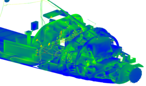
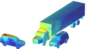
In automotive, autonomous driving presents a higher stakes circumstance where reliability and safety require high-quality EM sensor behavior for obstacle detection and collision avoidance, both long and short range, but also V2X. IDS solutions provide realistic predictive engineering, on scalable virtual models ranging from individual sensors through full systems integrated into virtual cars. By integrating such highly physical EM radar and communication systems simulations into driving scenarios, car manufacturers will be able to increase the safety and performance of autonomous vehicles.

Detailed performance simulation in context of Vehicle to Vehicle communication.

Siemens PLM Software
www.siemens.com/plm

Filed Under: Siemens PLM Tagged With: Siemens PLM

Siemens unveils Integrated Software Engineering solution for automotive embedded software

July 31, 2017 By Leslie Langnau Leave a Comment

Bruce Jenkins, Ora Research

The first fruits of Siemens’ 2015 acquisition of application lifecycle management (ALM) tool developer Polarion came to bear in a new Integrated Software Engineering solution for the automotive industry intended to address critical product development challenges stemming from the explosive growth of embedded software in today’s increasingly smart, connected, self-aware and situationally aware vehicles. For background on the acquisition, see our ALM-PLM integration challenges and opportunities.

By integrating ALM software with product lifecycle management (PLM) software, Siemens’ aim is to deliver a solution to help automakers seamlessly manage the inherently different engineering lifecycles of electromechanical systems and of the software used to control them. Key benefits:

  • Unites ALM with PLM.
  • Integrates embedded software and physical systems development.
  • Improves automotive product quality, software robustness and traceability.
  • Quality improvement aims to significantly reduce software-related recalls.

The goal is to help automotive engineering organizations enhance software functionality and traceability, and at the same time improve overall product quality and reduce automotive recalls associated with embedded software. Siemens said this will be the first in a series of announcements about the family of Digital Enterprise Industry Solutions developed by Siemens’ PLM Software business.

“As cars get more sophisticated—with features like collision avoidance, automatic parallel parking, and the advent of self-driving, autonomous vehicles—the need for software to control these functions will continue to accelerate, resulting in increased challenges for product development,” said Siemens PLM Software vice president of automotive and transportation Dave Lauzun. “By integrating ALM and its ability to manage the embedded software development process with PLM’s capacity to manage physical systems, Siemens is providing a way for automotive companies to more rapidly, efficiently and accurately develop the robust and high-quality mechatronic systems that will power the future of transportation.”

Challenges of synchronizing ALM and PLM

Managing embedded software development in close synchronization with the development of physical systems is a big challenge for automotive companies, Siemens observes. Due to their respective natures, product engineering and software engineering follow inherently different development lifecycles. Software development is managed separately, and interface validation with hardware is done only at predefined checkpoints.

Most automotive programs are managed on a three- to five-year cycle, Siemens explains. They follow a gate-based development paradigm with strict checkpoints and certifications. Software development, on the other hand, is incredibly fast-paced, as it follows agile processes where collaboration and rapid innovation are key. Typically, development of mechanical, electrical and electronic systems is managed within product lifecycle management (PLM) tools, while software development is managed with application lifecycle management (ALM) tools. The challenge is to combine these two inherently different product development methodologies. Software and hardware engineers working on their respective ALM and PLM applications must be able to access information across all lifecycle-related processes.

Spiraling vehicle complexity “exposing deficiencies of current processes, tools and methods”

“In an era of smart-connected cars, the interactions between software and physical systems are increasingly becoming more complex, exposing deficiencies of current processes, tools and methods,” Siemens pointedly, and correctly, observes. “A Digital Twin of vehicle systems capable of representing the complete physical and digital behavior of today’s IoT-connected cars is necessary to realize innovations.”

The company says its Integrated Software Engineering solution for the automotive industry “finally moves embedded software development into its proper place as an integral part of the full product lifecycle. This move is essential for automotive companies to thrive in the face of rapidly changing technologies, providing a new level of agility in automotive product development.”

Over the next several months, Siemens PLM Software says it will be launching a series of announcements about its Digital Enterprise Industry Solutions aimed at addressing pressing business needs for a wide variety of industries.

Siemens Integrated Software Engineering solution: https://www.plm.automation.siemens.com/en/automotive-transportation/automotive-software-development/index.cfm

Filed Under: Siemens PLM Tagged With: Siemens PLM

Siemens PLM to name Hemmelgarn CEO, Grindstaff executive chairman

September 27, 2016 By Mike Santora Leave a Comment

By Bruce Jenkins, President, Ora Research

Siemens PLM Software will appoint Tony Hemmelgarn president and CEO effective October 1. Hemmelgarn is currently the company’s executive vice president for global sales, marketing and services. Current president and CEO Chuck Grindstaff will become executive chairman of Siemens PLM.

Hemmelgarn, a seasoned industry executive, joined the company that would become Siemens PLM when Unigraphics Solutions merged with SDRC in 2001. He was SDRC’s Ford global account vice president at the time, and had been with SDRC since 1998. Previously he held both technical and sales/marketing executive positions with Intergraph.

Grindstaff joined the company in 1978 when it was known as Unigraphics Solutions, holding a variety of R&D positions during his first decade there. He then left the company to serve as president and CEO of Waveframe Corporation, which developed and manufactured digital signal processing systems for high-end motion picture applications. There he won a Scientific and Engineering Award from the Motion Picture Academy of the Arts and Sciences for the company’s groundbreaking work and its long-term impact on the industry.

On returning to Unigraphics in 1994, Grindstaff took over leadership of the Unigraphics product business unit before assuming a broader role as vice president of Unigraphics products and operations in 2000. In 2001, Unigraphics merged with SDRC to form the PLM business later known as UGS, which Siemens acquired and rebranded as Siemens PLM Software in 2007. In 2010 Grindstaff was appointed president, and also retained his position as chief technology officer for the organization. In 2011 he assumed the role of CEO.

Now, freed from day-to-day operational duties, Grindstaff can devote even greater focus than before to the development, realization and advancement of Siemens PLM’s vision for what it calls “digitalization”—the centerpiece of the company’s strategy and value proposition launched under Grindstaff’s leadership.

“Manufacturers must weave a digital thread through ideation, realization and utilization,” the company explains. “It’s not enough to digitize. That just mimics processes digitally for incremental improvement. You have to digitalize. Digitalization makes the digital thread of knowledge a proactive agent in driving your business. With a fully optimized ‘Digital Enterprise,’ you are better equipped to initiate or respond to disruptive innovation.”

brucejenkins_blog_2016-oct-no1_image1
Siemens PLM Smart Innovation Portfolio. Source: Siemens PLM

To help its customers “activate digitalization,” Siemens PLM is building what it terms a “Smart Innovation Portfolio.” This portfolio, the company says, delivers “engaged users who receive the right information at the right time—by transforming information so that only what’s relevant is delivered in a context suited to each person’s role; intelligent models that evolve throughout the process with the information necessary to optimize themselves for how they need to be built and how they should perform; realized products that achieve business goals through the integration of virtual product definition and real production execution; and an adaptive system that helps you efficiently deploy solutions today, while maintaining future flexibility.”

brucejenkins_blog_2016-oct-no1_image2
Smart Innovation Portfolio product families. Source: Siemens PLM

At the same time, Grindstaff will doubtless remain deeply engaged with the company’s customers, always one of his hallmarks as an executive, immersing himself in understanding their needs and helping foster their success through Siemens PLM solutions.

Ora Research
oraresearch.com

Filed Under: Siemens PLM, Siemens PLM & Events Tagged With: Siemens PLM

Siemens Releases Parasolid v27.1

December 17, 2014 By Barb Schmitz Leave a Comment

Today Siemens PLM announces the release of v27.1 of its Parasolid 3D solid modeling kernel. Parasolid is the foundation of Siemens PLM’s NX and Solid Edge products and is also licensed to many independent software vendors (ISVs) who develop hundreds of Parasolid-based applications in the product design and analysis market space.

Parasolid v27.1 delivers numerous enhancements to support efficiency and effectiveness in complex modeling workflows. These enhancements enable application developers to deliver step changes in productivity to end users.

Parasolid provides high-level geometric functionality that can be most productively and robustly achieved at the kernel modeler level, which allows application developers to focus on their customers’ other requirements.

Other improvements in Parasolid v27.1 include blending, surfacing, modeling support and platform support. These enhancements are in addition to numerous improvements targeted at specific industries and workflows.

Parasolid is the 3D solid modeling component software used as the foundation of Siemens PLM’s NX and Solid Edge products.

Let’s take a look at each area in which the product delivers enhancements.

Blending

Parasolid v27.1 provides extended control over the shape of blends. This extended control enables end users to get the exact shape required for functional or aesthetic purposes, which demonstrates the use of blending as a complex modeling technique beyond its historical role of simply rounding off model edges.

Blending enhancements allow you to:

* More easily control the profile of G2 face blends by providing constant depth and skew values
* Define variable radius edge blend parameters over a chain of edges – in addition to edge by edge – to give a smoother result

The left image shows a chain of variable radius edge blends defined edge by edge with the same parameters. The right image shows a chain of variable radius edge blends created in one operation with the same parameters.

Surfacing

Parasolid v27.1 enhancements give more flexibility to reach the desired design results within an operation, which eliminates multiple operations.

The surfacing enhancements allow you to:

* Replace sharp mitred corners created by sweeping a profile along a sharp non-G1 path with rounded corners
* Align parameterization of extruded surfaces with the extrude direction
* Optimize parameterization of the new face when replacing a set of faces with a single face
* Sweep a profile along a path with the option to extend the path beyond one or more faces used to lock the profile
* Sweep a solid tool along a path and specify that a face or set of faces of the tool are unimportant to the result and that their precise sweep should be replaced by a simpler capping surface

On the left is a traditional sweep of a tool body along a path. On the right, the red faces of the tool body are specified as unimportant to the result so their precise sweep is simplified to the red capping surface.

Modeling Support

Parasolid v27.1 includes changes to existing functionality to assist detailed modeling in fewer steps. Parasolid v27.1 modeling support enhancements allow you to:

* Imprint a set of curves that are coincident with a face as a group, which improves performance and robustness
* Imprint a curve onto faces of a body with greater influence by controlling how to imprint onto hidden faces

Platform Support

In response to customer requests, Parasolid v27.1 and Bodyshop v27.1 for Microsoft Windows are now compliant with the Microsoft Security Development Lifecycle, which is a set of standards designed to reduce incidences of security vulnerabilities in software. This is a precautionary platform security enhancement as there are no reports of security vulnerabilities in these libraries.

Filed Under: News Tagged With: Siemens PLM

Siemens Releases NX 10 Software

October 7, 2014 By Barb Schmitz Leave a Comment

The latest version of Siemens’ NX software has been released, touting among many things increased design flexibility and up to 3X higher productivity for users. New tools, such as the 2D concept development solution, make it easier and faster to create designs, while enhancements to NX Realize Shape software, a fully integrated sub-division modelling environment, provide designers with more flexibility to produce unique shapes.

A new optional touch-enabled interface provides expanded access to the full design capabilities of NX. And tighter integration to product lifecycle management (PLM) software–through Siemens’ Active Workspace environment–reduces the amount of time spent searching for product information. NX 10 also includes multiple enhancements throughout the integrated computer-aided design, manufacturing and engineering (CAD/CAM/CAE) solution.

These include:

2D concept development. Increasing product complexity makes 3D modeling the preferred method of product design throughout the world. However, in some industries including machinery and complex electronics, it is easier and faster to create initial design layouts in 2D. The new 2D concept development solution enables designers to explore concepts in 2D, making it up to three times faster to create new designs. Once the design is finalized it can easily be migrated to 3D to complete the model.

Enhancements to the NX Realize Shape. Enhanced solution give designers even more control over geometry modelling to produce products with highly stylized shapes or complex surfaces. NX Realize Shape is based on sub-division modelling, a mathematical approach to creating 3D geometry with smooth flowing shapes, pioneered by the entertainment industry. The tool is seamlessly integrated with NX which helps shorten product development time by eliminating the multiple steps associated with using separate tools for freeform design and engineering development.

Optional touch-enabled interface. This interface adds the flexibility of accessing NX on tablets running Microsoft’s Windows operating systems, making it easier to use NX when and where needed to enhance collaboration and productivity. Combining improved access to NX with tighter PLM integration through Active Workspace, the innovative interface to Siemens’ Teamcenter software, enables users to quickly find relevant information, even from multiple external data sources. Active Workspace can be accessed via the web on any device from any location.

NX Laminate Composites supports the new NX CAE environment for the LMS Samcef Solver, to create cohesive layers between extruded plies to model delamination.

Enhanced multiphysics capabilities. Significantly enhances simulation integration by connecting two or more solvers to streamline the process of performing complex simulations. The multiphysics environment delivers a consistent look and feel for performing multiphysics simulations so engineers can easily build coupled solutions on the same mesh using common element types, properties, boundary conditions, and solver controls and options.

Industry-specific capabilities in NX CAM. Helps engineers program faster and machine higher quality parts. New dynamically-adjusted roughing strategies automatically adapt to part geometry to enable better mold and die machining. New automated inspection programming capabilities in NX CMM (coordinate-measuring machines) enable the use of PMI (Product Manufacturing Information) to create inspection scanning paths. This helps significantly speed up the inspection process compared to the currently available touch point method.

Scanning inspection paths can be automatically created with NX CMM by using the embedded PMI data.

Production line design. NX 10 also includes new production line design capabilities for automotive assembly manufacturing. The new line designer application enables engineers to design and visualize layouts of production lines in NX, and use Teamcenter and Siemens’ Tecnomatix software to manage the designs, and validate and optimize manufacturing processes.

NX 10 will be available in December. For more detailed information on all the new functionality in NX 10, please visit here.

Barb Schmitz

Filed Under: News, Siemens Blogs, Siemens PLM Tagged With: Siemens PLM

7 New Year’s Resolutions for CAD Users

December 30, 2013 By Barb Schmitz Leave a Comment

As we approach year’s end and begin looking towards a brand-spanking new year, many of us will make New Year’s resolutions. These are often health-related (eat less, exercise more, drop a few pounds, quit an unhealthy habit or two) or family-related (yell at my kids less, be more considerate of my significant other, walk the dog more, etc.). Why not make a few work-related resolutions this year?

All engineers should occasionally take stock in where their career is at and the things they can do to advance it forward, whether at their current employer or to greener grasses elsewhere. So with this mantra in mind, I’ve decided to toss out a few New Year’s Resolutions to consider based on trends I’ve seen over the past year. Embrace them all, adapt a few, or ignore completely; it’s really your call. Or add a few of your own in the comment section.

Without further ado, here’s my list:

  1. Learn the basics of simulation. You’re a bonafide pro at your CAD system, but more and more companies are moving towards adapting simulation (FEA and CFD) into product development to lower prototyping costs and speed development. Take the initiative and sign up for an e-learning course online. NAFEMS offers code-independent classes that offer introductions to FEA and Fluid Mechanics, among many others. Check out the schedule and course titles here.
  2. Lobby for faster computers. One way to achieve an instant uptick in productivity is to rev up your computing power. Because of the booming popularity of tablets, the prices of PCs have plummeted. Their loss is your gain. Time to get your manager on board with a hardware upgrade. A four-core, Xeon-based PC with 16 GB of RAM and blistering-speed graphics will cost you less than $3K.  Spend $2K more and you’ll score an eight-core PC with 32 GB of RAM, solid-state disks and high-end graphics processing.

    High-end engineering workstations, such as this HP Z Workstation, are now super affordable, making this a great time to upgrade.
    High-end engineering workstations, such as this HP Z Workstation, are now super affordable, making this a great time to upgrade.
  3. Check out subscription-based CAD. If your company’s business is cyclical in nature (i.e. you only need CAD on a project basis), you might want to look into purchasing CAD, as well as add-on software, on a subscription basis. Several of the larger CAD vendors are now offering CAD tools on a monthly subscription basis, enabling smaller companies to move CAD from a capital expense to an operating expense. Siemens is now offering users access to full-fledged Solid Edge CAD software for a monthly subscription prices starting at $130. Give it a free 45-day test drive here.
  4. Become a better public speaker. Do you have ambitions of one day becoming a CAD or engineering manager? If so, keep in mind that managers must not only engage with staff engineers but also with executive management, customers, suppliers and outside agencies. Being comfortable speaking in front of others is not a talent all of us are born with so taking the time to develop these “soft” skills is important. Toastmasters International, a non-profit organization, is a great place to get your feet wet in public speaking.

  5. Investigate the cloud. Perhaps your company has avoided moving to the cloud for fear of IP security. Take the lead and look into the possible advantages the cloud could offer your company. Autodesk was the first to put CAD in the cloud with its Fusion 360 product, which offers excellent and easy-to-use data management tools and takes advantage of unlimited computing resources via the cloud. Autodesk also debuted the industry’s first CAM tool in the cloud, CAM 360, at this year’s Autodesk University. The company also offers SIM 360, simulation software in the cloud.

    Autodesk offers a cloud-based simulation tool, SIM 360, enables users to do mechanical FEA simulations anywhere at a fraction of the normal cost.
    Autodesk offers a cloud-based simulation tool, SIM 360, which enables users to do mechanical FEA simulations anywhere at a fraction of the normal cost.
  6. Try a new 3D modeling tool. There has been much debate in the CAD industry about which 3D modeling paradigm is best. Parametric modeling offers engineers a powerfully automated way of creating complex models, especially large assemblies that use families of parts. Direct modeling tools are easier to learn and use, changes are made through intuitive push-pull interactions and are ideal for concept development and collaboration. Might be a good time to try and learn both, as the either-or proposition seems to be ending. Mark your calendar: industry analyst Chad Jackson and leading experts from the CAD companies will be debating this topic in an upcoming Design World webinar on February 20th.
  7. Think like a businessman. Yes, I know you went to college to study engineering, not business, but companies more and more and looking for engineers who are business-savvy and innovative thinkers. They want engineers who have been involved with strategy and planning and know their way around a balance sheet. If you want to advance, you need to understand how the total costs to produce your company’s products affects bottom-line business decisions.

Barb Schmitz

Filed Under: Autodesk News, CAD Package, CAE, CFD, Company News, News, Siemens Blogs, Siemens PLM, Siemens PLM & Events Tagged With: Autodesk, cad software, Siemens PLM, simulation

The failed promise of parametric CAD, final chapter: A viable solution

November 18, 2013 By Evan Yares 5 Comments

Model reuse
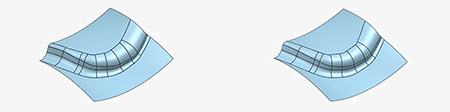
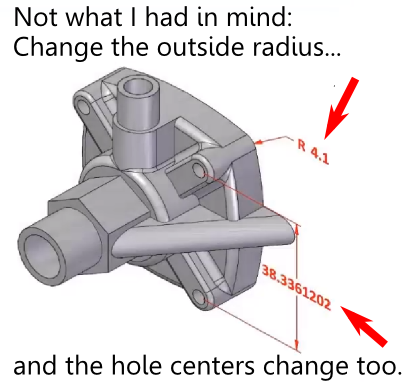
What is the failed promise of parametric CAD? In short, model reuse.

It’s a lot more difficult than it ought to be, for a variety of reasons. Several months back, I wrote a series of articles discussing those reasons, as well as some of the solutions that have come up over the years.  What was missing from the series was a final chapter; a detailed description of what could prove to be a viable solution to problems with model reuse: the resilient modeling strategy.

The resilient modeling strategy (RMS) is the brainchild of Richard “Dick” Gebhard. I wrote about Dick last June, in the article A Resilient Modeling Strategy. He’s a low-key guy with deep experience and serious expertise in the practical use of MCAD software. Over his career in CAD, he’s been a reseller for CADKEY, Pro/E, and most recently, Solid Edge.

RMS is a best practice for creating CAD models that are stable and easily reusable (even by inexperienced users.)  It can be learned and easily used by typical CAD users, it preserves design intent in models, and provides a mechanism by which managers or checkers can quickly validate a model’s quality.

Resilient Modeling Strategy

When Dick first started thinking about the concepts that make up the resilient modeling strategy, it was natural that it was in the context of showing the advantages of Synchronous Technology (The Siemens PLM brand name for its version of direct modeling.) In our discussions about RMS over the last year or so, I pointed out that, while I thought that RMS did indeed demonstrate the benefits of hybrid history/direct modeling in Solid Edge, for it to be taken seriously, and not be unfairly dismissed as a marketing initiative for Solid Edge, it needed to work with a wide variety of MCAD tools. I think Dick got where I was coming from, because he’s continued to refine and generalize RMS, with feedback from users of a number of MCAD systems.

In its current incarnation, RMS works particularly well with Solid Edge, as might be expected, but also works very well with Creo, NX, CATIA, and IronCAD (all of which are hybrid history/direct systems.) Further, with a few modifications, it can provide compelling value with SolidWorks, Inventor, and Pro/E (all of which are primarily history-oriented systems.)

It’s significant that RMS is also free to use. While Dick is available to provide presentations, seminars, and training, he has not attempted to patent, or keep as trade secrets, the underlying concepts of RMS. (He does claim a trademark on the term “Resilient Modeling Strategy,” which means that organizations offering commercial training on RMS will need to get Dick’s OK to use the term.)

Dick has posted an introductory presentation on RMS at resilientmodeling.com. While the entire presentation is 20 minutes long, the first 3-1/2 minutes cover the problems that people invariably experience when reusing or editing history-based CAD models. Watching that much will likely convince you to watch the rest.

On Wednesday, November 20, at 10:00 AM PST, Dick will be hosting a webinar on RMS. It’s scheduled to last just 30 minutes, with the emphasis on content, not hype. If you’re a serious CAD user or a CAD manager (or, for that matter, you work for an MCAD developer), it’ll be well worth your time to attend.

TL;DR: Resilient Modeling Strategy is a best practice for creating high quality reusable 3D MCAD models. It works with many CAD systems, it’s easy to learn and use, and it’s free. Big payoff for MCAD users. 

Presentation at resilientmodeling.com

Register for Nov 20 webinar on Resilient Modeling


Filed Under: Catia, Creo, Evan Yares, Featured, Inventor, News, Pro/Engineer, Siemens PLM, SolidWorks Tagged With: 3D CAD, Catia, Dassault Systemes, Evan Yares, Inventor, IronCAD, PTC, Siemens PLM, Solid Edge, SolidWorks

From aspirational engineering to design space exploration: engineering practices and tools for the 21st century

September 24, 2012 By Evan Yares 4 Comments


“This is why we test.” It was one of the comments to a YouTube video, showing a dramatic rear suspension failure while running a braking test on a Force Protection MRAP vehicle. Another comment pointed out that this was a first generation design, which had been greatly improved since the test.

When I saw the video, my first thought was that this was an example of aspirational engineering. That’s a polite way of saying “crossing your fingers, and hoping it will work,” rather than doing the up-front engineering to prove it will.

Don’t take what I’m saying wrong. Sometimes, the best way to engineer something is to not engineer it. If I were designing a suspension system for an MRAP, the first thing I’d do would be to look for commercially available alternatives that have already been engineered (such as, for example, the TAK-4 independent suspension, from Oshkosh.)

But, assuming I was in the position of needing to actually engineer the suspension, I don’t think I’d just draw it up, and hope it worked. I think I’d want to develop a practical and reliably replicable process, incorporating systems engineering and simulation, to gain confidence that, as a start, I was on the right conceptual track, and that the suspension would perform as designed—before manufacturing costs were incurred. And before warfighters were put in harm’s way by its potential failure.

Some defense contractors may not think this way (though, to be fair, MRAPs were rushed into the field with less engineering than typical, because our soldiers were facing IEDs with Hummvees—with fatal results.) Yet, the DoD Systems Engineering Research Center definitely thinks this way: Systems 2020 is their strategic initiative to transition the design, adaptation and manufacture of defense systems to “twenty-first century engineering practices and tools.”

Ever since I read the Systems 2020 report a couple of years ago, I’ve been mulling over this concept of bringing together the disparate processes used by engineers within their particular segments of the overall product development process. I’ve seen flashes of technologies that fit into this realm: Active Workspace, from Siemens PLM, Comet Workspace, from Comet Solutions, ModeFrontier, from Esteco. None of these are really PLM. They’re part of something beyond PLM. Something that doesn’t really have a name.

Or, maybe it does?

Last week, I got a note from Bruce Jenkins, of Ora Research. He’d read something I’d written on the importance of systems engineering, and asked the question “Why is it not more evident to everybody?”

Looking at the Ora Research website, I found Bruce’s discussion of design space exploration (DSE):

The most successful engineering projects begin with discovery – conceiving a rich array of ideas to solve a problem or address a need. But the power of such discovery is too often sacrificed to schedule pressures and resource constraints. Add to these the toolset barriers and hamstrung work processes that make it a struggle for discipline experts to look beyond their own silos and work more collaboratively as a team – to achieve the critical but elusive goal of gaining a system-level understanding of the project and their role in it, then acting on it. The result is familiar: engineering teams find themselves forced to settle on a design concept without high confidence that it’s the best, most cost-effective or most robust choice.

An emerging solution to this quandary is design space exploration (DSE), both a category of methods and a new generation of software tools that are beginning to radically advance the capabilities of engineers and multidisciplinary engineering teams to discover an array of possible design concepts early; rapidly and fluently evaluate tradeoffs, variants and sensitivities; then select the best and move to implement them.

This is the first time I’ve seen these multiple disciplines grouped together in such a cogent fashion. I think Bruce may have something here.

If you’re interested in twenty-first century engineering practices and tools, I recommend downloading the prospectus for Ora Research’s report on Design Space Exploration.

Filed Under: CAE, Evan Yares, Featured, Simulation Software Tagged With: Comet Solutions, Esteco, Ora Researcholutions, Siemens PLM

Should you use JT or 3D PDF?

August 31, 2012 By Evan Yares 9 Comments

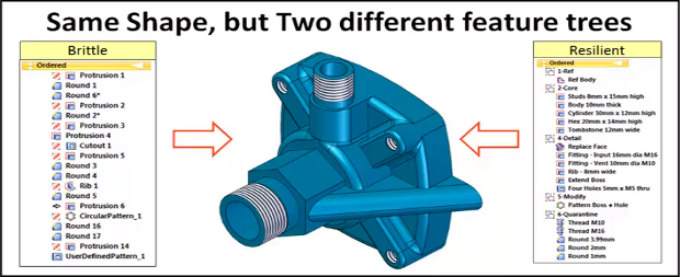
I always like a little controversy. Especially when it leads to more understanding.

A few days ago, Dennis Keating, a Senior Account Executive with Siemens PLM, posted this note about JT over on LinkedIn:

Try taking a look at Siemens and the international format for JT. It does not have any of the limitations of 3DPDF and works with all major CAD systems. A large Aerospace & Defense contractor is switching completely from Creo to NX to utilize NX’s PMI and JT and eliminating all 2D drawings. They will use PMI in all downstream applications CAM, CMM, Tooling & Fixturing, and variational analysis & simulation. They benchmarked WF5 & 2 Creo Beta releases and decided to standardize on NX & JT. PTC could not match the functionality and completeness of the NX & JT solutions for thier production environment. They completely eliminated 3DPDF as a solution because of the vast number of deficiencies in the product.

Those sound like good fighting words, don’t they?

Phil Sprier, who sits on the board of directors of the 3D PDF Consortium thought so. Here’s his reply:

Pretty bold and sweeping statements. What specifically are the limitations of 3D PDF that JT doesn’t have? What are the vast number of deficiencies in 3D PDF? Was it really limitations of 3D PDF that caused the unnamed, unconfirmed company to switch to Siemens?

At this point, Jim Merry, who works with Tetra4D (a company that makes 3D PDF authoring software), chimed in:

It is important to distinguish between the capabilities of formats like STEP, JT and 3D PDF and the capabilities of the various tools available to create and consume data in those formats. It’s quite easy to find examples of 3D content creation software that can export high fidelity examples of each as well as low fidelity. The low fidelity examples are not evidence of deficiencies in the formats.

From the end-user point of view, their data would export to one or all of these formats and they could choose the fidelity level to suit their business needs. They could then provide that file to anyone for use within a robust, feature rich, free and ubiquitously deployed application for consuming that data. The view of course is different from the various vendor’s points of view and herein lies the issue/opportunity.

And, to really make things interesting, David Opsahl, the Executive Director of the 3D PDF Consortium, jumped in:

I agree with the above comments. It isn’t enough to put out statements like that without knowing the context – what were the requirements? There are a HUGE number of use cases that JT can’t support because of “deficiencies” it has, which really aren’t deficiencies because JT wasn’t designed to support those things. Similarly there are use cases that JT is suited for that PDF is not. Was this customer attempting to use 3D PDF for things it wasn’t designed to do?

Look, I totally get that we all want to “promote” the products and standards we support. But putting out statements like this, without the backup detail, is irresponsible because you aren’t speaking to the community in a way that allows them to make an informed decision.

I find it extremely curious also that no mention is made of the fact that several of the Manufacturing Engineering products Siemens delivers make use of 3D PDF because of the lack of capability within the JT format. In other words, they are using 3D PDF precisely because JT wasn’t designed to support a large number of use cases. Doesn’t that speak directly to the fact that each has their place – it certainly would seem so.

I couldn’t help but give Davis a hard time (I know him, and he can take it):

David: That’s harsh, dude! Don’t scare Dennis away. I want the backup detail. On both JT and 3D PDF.

Here’s how he replied:

Wasn’t meant to be harsh. I think the point of your comment is the same as we are all saying – details matter. Without the details, its just a self-serving promotional statement. While promotional statements in general are something I’m not fond of, promotional statements that say “this is good” are one thing, but when you say “this is good, and this is bad,” without providing details, I think that crosses a line. The fact that certain Siemens products employ 3DPDF for certain use cases is well known throughout Siemens, so I can only conclude that the purpose of the statement is to scare people away from using 3DPDF and towards JT. The fact is that both have their uses and their intended purposes, and while it is true there may be some overlap, the fact is that overlap, in my view, is very small. If we are going to use communities and social media to inform, we need to exercise responsibility in how we avail ourselves of that right in my opinion.

And Dennis and I used to work together; he knows I’m a pussycat. :-)

He then added this clarification, for anyone reading the thread who might not be familiar with the issues:

I would like to add some additional thoughts for folks who are members of this group, who might be wondering what they should look for when trying to make sense of which formats matter. I can’t speak to Dennis’s intent specifically, but the implication is certainly there that 3DPDF is inferior to JT. Setting aside for the moment any variations in “fit for purpose”, or applicability to use cases, the potential evaluator or user should consider the following.

  • One can certainly compare any two (or more) formats for applicability to a certain use case. For instance, I might wish to compare JT to 3DPDF in their ability to accurately represent geometry or product manufacturing information (PMI). In the case of PDF, and 3DPDF in particular, I now have to pick *which* 3D format defintion I wish to use – U3D or PRC, as PDF supports both. At the end of the day, however, this is a comparison of *formats*. That’s all it is – a measure the *potential* of a tool or tools which support the format to solve my particular problem.
  • Formats in and of themselves do not accomplish anything, however. What does matter is how has the provider of the products involved *implemented* the format. Does it have the two key attributes – conformance, and quality – necessary to produce a successful outcome? The former is the degree to which a given implementation adheres to the standard as exemplified by the output of the application; the second is a measure of reliability – can it repeatedly produce results that are conforming to the standard? As with anything, the position of products in the market with regards to these two measures will vary. Some will support it well, others less so. It is important to note that the variation in conformance and quality observed in various products is *not* a format issue, but an implementation issue.
  • In competitive benchmarks, such as the one outlined above, it is also very true (and has been for many years) that if a standard format is to be used as a means to interchange data between products that all originate from the same developer, that it should be expected they can “tweak” the implementation to a great degree among their own products, and still not necessarily produce data that conforms to the specification. In this case, since Siemens/UG origniated JT, one would expect, and you would probably see, a high degree of conformance. However, as we all know, the world is not a homogeneous platform. It might be within one set of walls (a single company), but that has nothing to do with how well the data exchange or communication will work when it is necessary to work *outside*, with partners, suppliers, or customers. Here again, if everyone in a value chain decides to be homogeneous – AND – they also agree that the limits of which use cases can be accomplished with that set of tools is sufficient, then it *might* work.
  • Lastly, one cannot let the limitations of any format (and they ALL have limitations) define the bar of success. The simple fact is that there is no one format (JT, STEP, PLCS, PDF, etc.) that will address the spectrum of critical use cases in an organization. We might wish that were the case, because it would make life simpler, but its simply not going to happen in the foreseeable future.

Overall, I thought it was a rather enlightening conversation. Except—what about the differences between JT and 3D PDF?

I can tell you a few of them: JT is suitable for digital mock-up. 3D PDF isn’t. 3D PDF supports document-centric output, and is consumable by anyone who has Adobe Reader on their computers. JT not so much.

There are a lot more differences, but, really, I think we need to step back, and do a real side-by-side comparison of the two formats (and the tools used to author them), to better understand their strengths and weaknesses. What do you think? Would you be interested in seeing such a comparison?

Filed Under: Evan Yares, Featured Tagged With: 3D PDF Consortium, Siemens PLM

How was the Mars rover Curiosity designed? With Siemens PLM software

August 7, 2012 By Evan Yares Leave a Comment

Last Sunday night, I watched the live video feed from NASA’s Jet Propulsion Laboratory, as the rover Curiosity descended through the Martian atmosphere, and landed on the planet’s surface.

NASA called the process of landing the Curiosity “7 minutes of terror.” The whole process was completely automated—and all that the people at JPL (or the tens of thousands of us who were watching over the web) could do was wait, helplessly, as the drama played out. When Curiosity landed safely, and sent its first pictures from Mars’ surface, cheers rang out—not just at JPL, but on Twitter and other social media sites.

One of the things I noticed immediately, when I tuned into www.nasa.gov was that the average age of the scientists and engineers shown in the feed was quite young. I’d noticed this before, in a video segment shot by PhD Comics inside the Mars Rover Test lab, where NASA engineers Chaz Morantz and Bobak Ferdowski talked about Curiosity.

It’s not your father’s NASA anymore.

The Curiosity is the largest and most advanced space exploration robot ever made. It was designed with Siemens PLM software, including TeamCenter and NX, and is almost a best-in class example using those to tools, from conceptual design, to full-system simulation. (To understand why I say “almost,” keep reading.)

Here are a few videos that discuss Siemens PLM’s involvement with the Curiosity rover project:

Here is Daren Rhoades, who works for Siemens PLM, and used to work for JPL, explaining some of the challenges in designing Curiosity:

Doug McCuiston, Director of the Mars Exploration Program, talking about the importance of Siemens PLM software in designing Curiosity:

You can watch these, and other videos here.

Almost a best-in-class example.

In the videos, NASA’s Doug McCuiston says: “The challenges of building something like that, with all the parts that are involved—all the discrete parts, all the interfaces, and all the testing, and the ability to maintain not just the documentation, but all the drawings, the test flows, the verification items, is a very complex task in itself.”

No kidding.

Yet, if NASA were to design Curiosity today, I suspect they’d want to take a serious look at a couple of advancements in Siemens PLM software could make their life quite a bit easier.

Active Workspace

The first is a product called Active Workspace. Siemens calls it “a personal environment for accessing your entire PLM system.” You can download a fact sheet for it here.

I was lucky enough to be able to Active Workspace before its public announcement, and talk to some of the key people behind its development. The product includes a lot of really valuable capabilities, incluidng product data navigation and visualization, visual reporting, shared contexts, flexible collaboration, and ridiculously powerful search (including shape search.)

But what completely surprised me was that it goes way beyond just letting you view relationships between parts. It lets you view relationships between all of your product information, including requirements, functions, logical diagrams, and systems-engineering information.

Let me put that in a different way: Active Workpace supports a systems engineering driven product development process. It is systems engineering that lets you link together all the disparate elements of a product design into an intelligent product model, which can be continuously validated. It is the key to enabling true model-based development.

Here’s Chuck Grindstaff, CEO of Siemens PLM Software, talking about systems engineering and Active Workspace:

Product and Manufacturing Information

The other advancement from Siemens PLM that NASA would benefit from isn’t entirely new, but it’s become increasingly important: PMI (Product and Manufacturing Information.)

If you watch the videos about Curiosity, you’ll notice that they talk about “drawings.” CAD drawings have been around a long time—but that doesn’t mean they’re a good thing. They’re designed for human interpretation, and are thus subject to human misinterpretation. And they create a disconnect between product design and manufacturing.

PMI can contain GD&T, weld symbols, text and dimensions, as well as the product definition and process notes. PMI can exist in 3D models in the same way that information exists on 2D drawings – using leader lines that connect the data to specific parts in the product design.

The use of PMI shortens the design cycle by enabling product teams to incorporate product and process information during the design phase. This results in better communication between design and manufacturing groups, fewer errors, streamlined design and manufacturing processes and faster change management. PMI not only reduces the need to generate 2D drawings; it also enables downstream applications to directly access this information for automating tasks such as CNC programming, tolerance stack up analysis and CMM analysis.

Here’s what Norm Crawford, of Applied Geometrics, has to say about PMI: “Through the use of 3D documentation methods (i.e., PMI), the time and cost of documenting a part can be reduced by 50 percent and make early involvement of manufacturing easier with state of the art online 3D collaboration and visualization tools. Limiting redundant annotation and views – normally created on drawings in an attempt to clarify part design requirements – leads to better communications with fewer interruption errors, improved first time quality and increased productivity.”

You can watch a video about NX PMI here.

Now, as for NASA: they may well be using PMI already. NX has supported PMI for many years. If they produced 2D drawings for the Curiosity rover, it may have been a crutch (because of some immaturity in NX’s support for PMI at the time), or it may have been just a matter of habit. (CAD people love their drawings, and don’t want to give them up.) In either case, today’s NX supports PMI well enough that there’s no reason to create 2D drawings. And many reasons not to.


Filed Under: Evan Yares, Siemens PLM, Siemens PLM & Events Tagged With: Siemens PLM

  • Go to page 1
  • Go to page 2
  • Go to page 3
  • Go to Next Page »

Primary Sidebar

3D CAD NEWSLETTERS

MakePartsFast

Footer

3D CAD World logo

DESIGN WORLD NETWORK

Design World Online
The Robot Report
Coupling Tips
Motion Control Tips
Linear Motion Tips
Bearing Tips

3D CAD WORLD

  • Subscribe to our newsletter
  • Advertise with us
  • Contact us
Follow us on Twitter Add us on Facebook Add us on LinkedIn Add us on Instagram Add us on YouTube

3D CAD World - Copyright © 2022 · WTWH Media LLC and its licensors. All rights reserved.
The material on this site may not be reproduced, distributed, transmitted, cached or otherwise used, except with the prior written permission of WTWH Media.

Privacy Policy