
Today’s release of SprutCAM X 17.0.11 introduces a host of enhancements, compatibility with MOKA robots, and bug fixes.
Key features of the new release include:
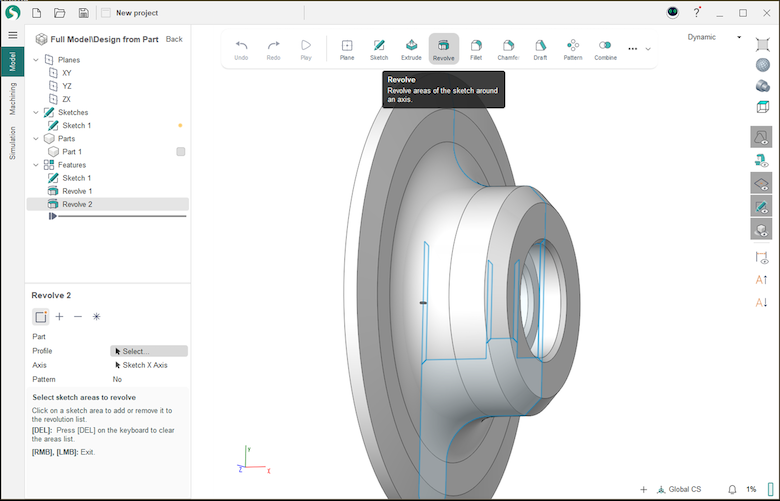
- Enhanced .dxf format support: SprutCAM X enables users to import sketches in .dxf format and seamlessly convert them into sketches within the build-in 3D CAD module. This enhancement facilitates the creation of 3D models of parts for machining projects based on imported sketches.
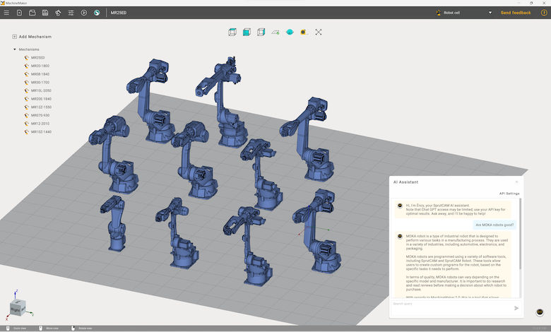
- Expanded compatibility: The development team added MOKA industrial robots to MachineMaker, the application for creating digital twins of equipment in SprutCAM X Robot. Wuhu Moka Robot Technology has more than 10 series of industrial robot products, including hollow welding robots, handling robots, loading and unloading robots, special robots for die-casting and grinding, stamping robots, etc. The Robot Components Library now includes the following MOKA robot models: MR07S-930, MR08-1840, MR10L-2050, MR10Z-1440, MR12-2010, MR12Z-1550, MR20-1800, MR20E-1840, MR25ED, and MR30-1700.
- Improved smart hints: Updates to Roughing Waterline, Finishing Waterline, 2D Contouring, and Pocketing operations with enhanced smart hints for a more user-friendly experience.
- Configuration enhancements: The development team updated the list of operations for the 2.5D Milling configuration and added Chamfering and 2.5D Contouring operations to the Cutting configuration for robotic machining.
- User interface improvements: The font size in the CLData Viewer (post processor debugging application) interface has been updated for improved readability. Updates to the Approach/Return tab in G-code based operations.
The SprutCAM X 17.0.11 release includes a comprehensive set of bug fixes and addresses issues of the software stability, reliability, and performance enhancements.
Users with an active software maintenance contract have already received notifications about the new release and are encouraged to proceed with the update. For those without notification, please contact your nearest SprutCAM X Reseller for assistance.
SprutCAM
sprutcam.com


 Design Power Mobile is the next revolution in belt drive engineering and management. Gates Design Power is the home for all Gates power transmission digital design tools, and the new mobile version provides its customers and staff with features to support belt drive system engineering in the palm of their hands.