• Skip to primary navigation
  • Skip to main content
  • Skip to primary sidebar
  • Skip to footer

3D CAD World

Over 50,000 3D CAD Tips & Tutorials. 3D CAD News by applications and CAD industry news.

  • 3D CAD Package Tips
    • Alibre
    • Autodesk
    • Catia
    • Creo
    • Inventor
    • Onshape
    • Pro/Engineer
    • Siemens PLM
    • SolidWorks
    • SpaceClaim
  • CAD Hardware
  • CAD Industry News
    • Company News
      • Autodesk News
      • Catia News & Events
      • PTC News
      • Siemens PLM & Events
      • SolidWorks News & Events
      • SpaceClaim News
    • Rapid Prototyping
    • Simulation Software
  • Prototype Parts
  • User Forums
    • MCAD Central
    • 3D CAD Forums
    • Engineering Exchange
  • CAD Resources
    • 3D CAD Models
  • Videos

Barb Schmitz

Mobile Apps for Designers and Engineers on the Go

January 15, 2015 By Barb Schmitz 1 Comment

Mobile apps for consumers have proliferated over the past several years, becoming somewhat of an ubiquitous part of our everyday lives. We think nothing of checking weather updates, movie schedules, and bank balances while we’re on the move, so why has it taken so long for mobile apps to hit big when it comes to engineering and manufacturing?

Certainly there’s an opportunity for vendors to offer apps for engineers that improve their mobility and offer access to at least some of the same tools they would have in the office. I wrote a blog post, Is CAD Becoming More Portable? in late 2013. Since then, however, it doesn’t seem like a lot of progress has been made on the CAD mobility front.

While this might be true, there are still many handy mobile tools and apps that engineers can use on a daily basis to capture ideas and concepts, view drawings and models, and collaborate with other stakeholders.

In a blog on the topic of mobile apps for engineers, written by David Chadwick of Siemens, he discusses how maintenance engineers would find it useful to have spare parts catalogs available on mobile devices. They could find the correct spare part, check if it was in their stores, and if not order the part immediately, all while working in a remote part of the factory.

Fortunately such technology now exists. CADENAS’ PARTsolutions software offers direct mobile access to more than 600 certified standard parts catalogs from international manufacturers on both iOS and Android mobile devices.

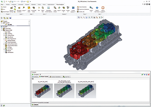
Chadwick believes that the increasing availability of mobile apps for designers and engineers will have a big impact on their productivity and effectiveness. For manufacturing organizations, this could include the product designer being able to rapidly retrieve 3D models and drawings of products when on the shop floor to help solve a problem that has been encountered in the manufacturing process.

For field engineers being able to quickly access specifications and drawings for a machine that they are installing at a remote site. When traveling designers can have access to their design information and can answer questions and progress their projects when they are waiting at an airport or riding on a train. When meeting with suppliers and customers, the immediate availability of design data can help them to resolve issues immediately instead of having to first return to the office to find the information they need.

Mobile apps for engineers

While this is not a comprehensive list, here are a few mobile apps that are worth checking out for engineers on the go.

* Sketchbook Mobile. This affordable professional drawing and painting tool is a good starting point when ideas arise while you’re in the field. Available on Android and iOS.

* Autodesk AutoCAD 360. This DWG file viewer allows users to view, edit, and share their 3D models with others using the iPhone or iPad. This app is probably the most downloaded of the CAD viewer apps with more than 5 million installs on the Android platform alone. It’s available on Android and iOS.

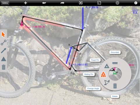
* ForceEffect. Also from Autodesk, this app allows users to simulate design concepts on the spot. It does all the heavy lifting (simulation and calculations) on the mobile device. This makes it easy to simulate design options during the concept phase for easy validation.

Autodesk's ForceEffect allows you to create a design, give it a set of supports, introduce forces upon it, see how other forces come into play and how changing that design changes those forces.
Autodesk’s ForceEffect allows you to create a design, give it a set of supports, introduce forces upon it, see how other forces come into play and how changing that design changes those forces.

* GrabCAD. For anybody using GrabCAD Workbench, this mobile app provides access to both the GrabCAD public library and your private projects stored on the GrabCAD Workbench. View models, comment, create projects, and get update notifications–all from your Android or iPhone/iPad.

* Engineering Unit Converter is popular, with more than 100,000 installs and many happy customer reviews. The best part? The app uses less than 1 MB of space on your system. The downside? It’s only available for Android.

* Solid Edge Mobile Viewer. Download this new Windows 8.1 app for free from the Windows Store to view 3D part and assembly models, and 2D drawings that were created using Solid Edge. Available for iOS and Android as well.

* eDrawings Pro. This app works with SolidWorks, DWG and DWF (DraftSight) files. Users can view different model configurations, drawings and exploded views for different representations. Images can be rotated, zoomed, and minimized to measure distances in relation to the model. Users can make connotations, markups, and cross-section views while taking photos and snapshots, which can then be emailed for others to view.

The newest version of eDrawings Pro lets users see their 3D models in a real-world setting through augmented reality. The app takes the 3D model and places it in position anywhere the user wants simply by turning on a mobile device camera.

* Engineering Cookbook. Provides access to frequently needed information, including HVAC load estimates, design formulas, conversion factors, and sound and system design guidelines. Available on Android and iOS.

* Engineering Handbook Lite. Similar to the Engineering Cookbook but also offers materials classifications and engineering components, which allow users to calculate maximum/minimum values from things such as a hole to a shaft and back again. A mechanics feature allows users to view the formulas for gear drives and their dimensions, which is especially convenient when using a 3D printer to fabricate parts.

Are there any mobile apps for engineers that I didn’t list that you are using and loving? If so, please share them in the comment section below.

Barb Schmitz

Filed Under: Autodesk, News, Siemens PLM, SolidWorks Tagged With: Autodesk, Siemens, SolidWorks

7 Most Popular 3D CAD World Blog Posts of 2014

December 29, 2014 By Barb Schmitz Leave a Comment

As 2014 comes to a close and we look upon a fresh, new year, many of us reflect on what’s happened–both good and bad–throughout the year. We’re doing the same here at 3D CAD World. With this thought in mind, we thought we’d take a walk back through the year and share with you all some of the most popular 3D CAD World blog posts of 2014.

Without further ado, here are the top 7 blog posts of 2014 in order of popularity.

1. 7 Career Tips for Engineers. There’s more to being a successful engineer than being good at math and science. Check out this blog post for tips and strategies you can employ to increase your chances of career advancement, some of which might be surprising.

2. 10 Tips for Writing a Better Functional Specification. Every design project starts with the creation of a formal functional specification, which becomes the roadmap by which all design participants must travel to hopefully arrive at a successful product launch. Check out this post for some how-to tips for writing a functional spec that will help guide the efforts of design team members and ensure that the project’s objections are met.

Comic courtesy of J. King, ModernAnalyst.com.

3. Will CAD Subscriptions Shatter Cost Barriers to Entry. Subscription sales models allow users to pay for CAD software on a monthly basis or on an as-they-need-it basis, eliminating the high upfront cost of CAD and enabling companies to move CAD from a capital expense to an operating expense. The goal is to open up high-end 3D CAD tools to users at smaller companies with low-end budgets as well as those in more cyclical businesses, somewhat untapped markets.

4. 10 Reasons CAD Standards are Still Important. The introduction of a new CAD standard can be a disruptive and time-consuming process, but the risk for companies is that the longer they continue with an inefficient system, the more disruptive, time consuming, and ultimately costly it becomes to replace it when they later have more staff and project work attached to it.

Cartoon courtesy of Roger Penwill.

5. 10 Holiday Gift Ideas for Engineers. Engineers are a special breed of people, and as such, they need special gifts. Though many of you reading this post probably are engineers, share this list with your loved ones, who let’s face it, don’t get you and your left-brained nature. You love gifts that make you think, that challenge you and put your particular brand of smarts to use.

6. Top Ten Tech Predictions for 2015. As the end of the year quickly approaches, we look ahead to 2015 to see what new technologies are poised to disrupt the status quo for all of us. Every year, IDC issues a report that predicts what technologies will be the most significant. Click through to see which of the tech trends IDC predicts will be most disruptive to the status quo in 2015.

Wearables will see an explosion of innovation in 2015, but unit sales will underwhelm.

7. Autodesk Acquires Nastran NEI Solver. In May Autodesk announced that it had acquired the Nastran solver from NEi Software. To be clear, this is not the Nastran that was based on the original NASA-sponsored code. NEi Nastran, however, is often benchmarked against the original Nastran as well as ANSYS and Abacus. Though the company has yet to unveil its plans for the software, it is speculated that the company will add the solver’s powerful linear and nonlinear as well as dynamic response capabilities to the other solvers the company has acquired in recent years.

Barb Schmitz

Filed Under: News Tagged With: Autodesk

Santa Tests New Sleigh Design With ANSYS

December 23, 2014 By Barb Schmitz Leave a Comment

As the year winds down and the holidays approach, new product introductions and corporate news grinds to a halt, leaving editors like myself on a somewhat desperate search for news to cover and share with readers.

So it was with great delight that I came across a blog post, written by Gilles Eggenspieler, a senior product line manager at ANSYS. It appears that Santa has been having some sleigh problems. His legendary mode of transportation–used to distribute toys and gifts globally–had broken down during delivery.

Designing a better sleigh

Fortunately he had to look no further than employees at ANSYS who decided to put their simulation and 3D modeling software to work to build Santa a better sleigh.

Santa had two key requests:

* The sleigh needs to be more deer-energy efficient
* The sleigh needs to protect Santa from harsh environments

Eggenspieler recruited three of his colleagues–Brian Bueno, Simon Pereira and Robin Steed–to assist with the redesign. Their first task was to study the current design. “One thing that was obviously clear to us was that Santa did not have any protection from the wind,” says Eggenspieler, “but using computational fluid dynamics (CFD) simulation results also showed that the sleigh drag was very high.”

Santa’s sleigh with flow recirculation region in gray – the larger the recirculation regions, the larger the drag.

After studying Santa’s existing sleigh design, the team set up the task of designing a new one. Brian Bueno took the lead using ANSYS SpaceClaim software to design the new sleigh. Then Eggenspieler conducted the CFD simulation, and Robin Steed used his visualization skills to prepare the post-processed results, which were very promising.

Santa's new sleigh created in ANSYS SpaceClaim software.
Santa’s new sleigh created in ANSYS SpaceClaim software.

Apparently Santa was thrilled with the result, especially when he was told that if he gets delayed, he can safely switch the sleigh to supersonic speed. The team even added a stealth mode so Santa could be incognito, if necessary.

Santa's sleigh at supersonic speed, one can clearly see the shock wave occurring as soon as speed is about Mach 1.
Santa’s sleigh at supersonic speed, one can clearly see the shock wave occurring as soon as speed is about Mach 1.

The sleigh was built, and tests showed that CFD simulation predicted the sleigh performance pretty well. As of today, the sleigh successfully passed (hyper secret) FAA certification and Rudolph was just certified on this new equipment. You can read the blog post, Santa Puts ANSYS to the Test for New Sleigh Design here.

Happy Holidays everyone!

Barb Schmitz

Filed Under: CAE, News, SpaceClaim News Tagged With: ANSYS

COMSOL Releases COMSOL Server

December 19, 2014 By Barb Schmitz Leave a Comment

COMSOL announced yesterday the release of COMSOL Server, a new product designed specifically for running applications created with the company’s Application Builder. Released at the end of October, the Application Builder allows COMSOL Multiphysics software users to build an intuitive interface around their COMSOL model that can be run by anyone–even those without prior simulation experience.

COMSOL Server enables the distribution of applications, allowing design teams, production departments and others to share applications throughout an organization using a Windows-native client or web browser. By propagating the use of simulation throughout the organization, design cycles can be shortened and product quality greatly increased.

The dashboard and Application Library in the COMSOL Server web interface. From the app icon, you can launch an application, make it one of your favorites, and edit permissions. The dashboard also lets you view the apps that are already running as well as access other menu items such as the Monitor tool.

Build and Run Simulation Applications

COMSOL Server is the engine for running COMSOL apps and the hub for controlling their deployment, distribution, and use. After creating an app with the Application Builder, the server provides engineers and researchers with a cost-effective solution for managing how the app is used, either within their organization or externally to a worldwide audience.

“COMSOL Server provides an environment for running applications created in the Application Builder that is easy to access and use,” says Svante Littmarck, President and CEO of the COMSOL Group. “Using the Application Builder and COMSOL Server together, an R&D engineer, for example, has the tools to create applications that will best serve their specific industry in a format that is easy to use, quick to implement, and can be scaled for global benefit.”

With COMSOL Server, applications can be run in a COMSOL Client for Windows or in Google Chrome, Firefox, Internet Explorer, Safari, and other major web browsers. COMSOL Server can be hosted in a corporate network or in the cloud.

“COMSOL Server not only provides an effective way for engineers to distribute their applications, it also allows updates to be readily available to all users,” says Bjorn Sjodin, VP of Product Management at COMSOL, Inc. “Because applications are accessible through a web interface, as soon as a new version of an application is uploaded, app users will immediately have access to the latest version. Developers will also appreciate the fact that the applications can be password protected.”

To learn more about COMSOL Server and Application Builder, check out the recorded webinar “How to Build and Run COMSOL Simulation Apps.” Watch the archived version here.

Barb Schmitz

Filed Under: CAE, News, Simulation Software Tagged With: COMSOL

Siemens Releases Parasolid v27.1

December 17, 2014 By Barb Schmitz Leave a Comment

Today Siemens PLM announces the release of v27.1 of its Parasolid 3D solid modeling kernel. Parasolid is the foundation of Siemens PLM’s NX and Solid Edge products and is also licensed to many independent software vendors (ISVs) who develop hundreds of Parasolid-based applications in the product design and analysis market space.

Parasolid v27.1 delivers numerous enhancements to support efficiency and effectiveness in complex modeling workflows. These enhancements enable application developers to deliver step changes in productivity to end users.

Parasolid provides high-level geometric functionality that can be most productively and robustly achieved at the kernel modeler level, which allows application developers to focus on their customers’ other requirements.

Other improvements in Parasolid v27.1 include blending, surfacing, modeling support and platform support. These enhancements are in addition to numerous improvements targeted at specific industries and workflows.

Parasolid is the 3D solid modeling component software used as the foundation of Siemens PLM’s NX and Solid Edge products.

Let’s take a look at each area in which the product delivers enhancements.

Blending

Parasolid v27.1 provides extended control over the shape of blends. This extended control enables end users to get the exact shape required for functional or aesthetic purposes, which demonstrates the use of blending as a complex modeling technique beyond its historical role of simply rounding off model edges.

Blending enhancements allow you to:

* More easily control the profile of G2 face blends by providing constant depth and skew values
* Define variable radius edge blend parameters over a chain of edges – in addition to edge by edge – to give a smoother result

The left image shows a chain of variable radius edge blends defined edge by edge with the same parameters. The right image shows a chain of variable radius edge blends created in one operation with the same parameters.

Surfacing

Parasolid v27.1 enhancements give more flexibility to reach the desired design results within an operation, which eliminates multiple operations.

The surfacing enhancements allow you to:

* Replace sharp mitred corners created by sweeping a profile along a sharp non-G1 path with rounded corners
* Align parameterization of extruded surfaces with the extrude direction
* Optimize parameterization of the new face when replacing a set of faces with a single face
* Sweep a profile along a path with the option to extend the path beyond one or more faces used to lock the profile
* Sweep a solid tool along a path and specify that a face or set of faces of the tool are unimportant to the result and that their precise sweep should be replaced by a simpler capping surface

On the left is a traditional sweep of a tool body along a path. On the right, the red faces of the tool body are specified as unimportant to the result so their precise sweep is simplified to the red capping surface.

Modeling Support

Parasolid v27.1 includes changes to existing functionality to assist detailed modeling in fewer steps. Parasolid v27.1 modeling support enhancements allow you to:

* Imprint a set of curves that are coincident with a face as a group, which improves performance and robustness
* Imprint a curve onto faces of a body with greater influence by controlling how to imprint onto hidden faces

Platform Support

In response to customer requests, Parasolid v27.1 and Bodyshop v27.1 for Microsoft Windows are now compliant with the Microsoft Security Development Lifecycle, which is a set of standards designed to reduce incidences of security vulnerabilities in software. This is a precautionary platform security enhancement as there are no reports of security vulnerabilities in these libraries.

Filed Under: News Tagged With: Siemens PLM

10 Holiday Gift Ideas for Engineers

December 16, 2014 By Barb Schmitz Leave a Comment

We all know that engineers are a special breed of people, and as such, they need special gifts. Though many of you reading this post probably are engineers, share this list with your loved ones, who let’s face it, don’t get you and your left-brained nature. You love gifts that make you think, that challenge you and put your particular brand of smarts to use.

So without further delay, let’s get to those gift ideas that you can both give–and hopefully receive–that will keep you busy and happy on Christmas day.

1. OWI Robotic Arm. Let’s face it; most engineers have a thing for robots so don’t you think most of them would love a robotic arm to help them with their work? While, this one might not be able to do too many sophisticated things, but it’s still fun to build and to play with once it’s done, like shaking hands and getting it to pick up items. Find it here on Amazon for just over $50.

RoboticArm

2. The Parrot Rolling Spider. This ultra-compact drone, controlled by your smartphone, will impress even the biggest technophile on your list. The Parrot Rolling Spider, which was designed using SolidWorks software, flies indoors and outdoors with surprising speed and stability. Learn how to pilot via the FreeFlight 3 app, which can be downloaded for free on iOS, Android, and on Windows 8.1 and Windows Phone 8.1. You can find it a list of available retailers here.

rolling_hand

3. Math Formulas Tie. OK, so we all know that engineers as a whole are not known for their flair for fashion, but wearing this tie, which is loaded up with math formulas, will let everyone know that there’s an engineering brain at work. Just when you think ties are a passe gift, you find one that suits them to a tee and is something they’ll really enjoy wearing. Available for $45 at Uncommongoods.com.

Math-Formulas-Tie

4. Cams & Cranks. This one is perfect for those future engineers out there. Engino Mechanical Science: Cams and Cranks will help them learn all about cams and cranks and how they work together to convert energy. This line of toys is particularly made for those looking to help kickstart a child’s imagination and scientific reasoning. Get it for less than $25 here on Amazon.

Cams-Cranks-Set

5. Remote Controlled Machines. These Thames and Kosmos machines will do their bidding once they’re built and programmed to do so. Half the fun is making them and the other half is getting them to do what you want them to do. The engineers and other gear heads in your life will have fun tinkering with them and figuring out how they work. They are available here on Amazon for $70.

Remote-Control-Machines

6. Hanz Inventor’s Kit. A smartphone holder is just one of the things that you can put together with this kit. Budding engineers can create gadgets using it to create cool stuff, promoting originality and inspiring future designers. Includes 10 “Brains,” 20 Beams, 4 Wheels, 4 Tires, 6 Rubber Bands, and instructions on how to build ideas. Find it on Amazon here.

Hanz-Inventors-Kit

7. I’m an Engineer Mug. Alright, so the engineer in your life may have to rely on the spellcheck, but they don’t need much assistance when it comes to math problems. It shows that engineers can have a sense of humor, even if they’re paid to be very pragmatic. Order it on Amazon for less than $20 here.

Im-An-Engineer-Mug

8. The Coolest Cooler. Though not available yet, get your loved ones on the preorder list—and save $50—for the Coolest Cooler. Launched via Kickstarter, this cooler features an 18-volt, battery-powered rechargeable blender, 5-watt Bluetooth speakers, a USB charger, an LED lid light, locking gear tie-down, a divider/cutting board, and extra wide, easy rolling wheels. When it’s time to party, this cooler parties hard.

the-coolest-cooler-13271

9. The Jawbone Up24. This cool fitness wearable is an incredibly easy-to-use and enjoyable fitness tracker that counts steps, sleep, and calories. The Up24 is water-resistant, light, and comfortable to wear. The device syncs with iPhones and Android phones over Bluetooth. Only wearable rated as Excellent by CNET.com on its list of the Best Wearables of 2014.

up24@1x

10. Rocket Launch Set. Though it’s not exactly rocket science, they’ll have a lot of fun getting this rocket off the ground. Understanding the physics behind why it works will only add to the enjoyment for an engineer. Uses a standard Estes engines, this rocket can be blasted up to amazing heights of 1,000 feet. Available for approximately $20 from Amazon. Find it here.

Rocket-Launch-Set

Do you have any other creative gift ideas for engineers? If so, please feel free to add them below.

Barb Schmitz

Filed Under: News Tagged With: SolidWorks

AU 2014: Embracing a World of Design Disruption

December 12, 2014 By Barb Schmitz Leave a Comment

Autodesk University–as always–was a world wind of activity. Ten thousand design enthusiasts descending upon the Mandalay Bay Hotel and Conference Center in Las Vegas cannot be characterized as anything but a bit chaotic, however, upon reflection–and a few nights of much-needed sleep–I can now look back and share some of the key takeaways from the event.

I would say the word I heard most throughout the event was “disruption,” in this case meaning technologies that are going to radically change the way we think and do design and manufacturing. These disruptive technologies include 3D printing, the cloud, generative design, and the Internet of Things (IoT)–all of which Autodesk is embracing, both with products and industry initiatives.

Generative Design: Supporting the way decisions are made naturally

Autodesk CTO Jeff Kowalski kicked things off in the opening session giving attendees a glimpse of what lies ahead for design. He spoke of the importance of infusing “life” into current designs or products that are dead. Computers and design tools, he said, should be “portals to greater exploration” and that we all should be looking at design through the “lens of nature.”

How might this be done? He suggests through the use of Generative Design that starts with your design intent and then explores all of the possible ways to find a solution through multiple, successive generations, until the best is found.

Not not entirely new, generative design is really something only afforded to those with access to data centers, such as research institutes and large enterprises. In the future, however, with high-performance computing (HPC) centers, remote hardware accessed through the Cloud, and virtualization, generative design will be more widely available to the masses, so we can “stop starting from scratch when designing.”

The idea of Generative Design is being tested out in a research project, called Dreamcatcher that represents a new paradigm of workflow, one that blends the designers with artificial intelligence and cloud-based computing. Certainly quite interesting and I, for one, will be keeping a close eye on this project.

Autodesk has been working on computational design for the last seven years through research projects such as Project Dreamcatcher, a system that generates CAD geometry based on a list of functional requirements.

The Cloud

Autodesk really has been the first of the CAD vendors to wholeheartedly support cloud-based CAD. Nearly all of the products mentioned during the event were cloud-based. If you remember it was back in December of 2009, when Autodesk CEO Carl Bass first unveiled his vision for cloud-based CAD. Though there were many doubters five years ago, the Autodesk Cloud strategy is still moving ahead full steam with more and more products being ported to the cloud.

Today the concept of running CAD from a browser window is increasingly becoming common practice with many CAD vendors now seeking to beef up their desktop licenses with cloud-based offerings. Autodesk’s goal is clearly to move customers from perpetual licensing to access-based licensing and is a very attractive option for smaller companies and startups with limited budgets. Cloud services and subscriptions are the cornerstones of Autodesk’s plan to capture the new consumers, who are less likely to desire software ownership, more willing to pay for on-demand access.

Autodesk software now free to all students

During his address, Carl Bass announced the company’s new program to provide all Autodesk products free to all students, teachers, and schools globally. While the initiative seems philanthropic at first glance, at its heart it is also strategically shrewd. Just as its competitor SolidWorks has amassed millions of loyal college engineering students well versed in SolidWorks, thanks to aggressive student pricing, Autodesk obviously hopes to cultivate brand loyalty among the young designers of the future.

Autodesk education licensing contributes about U.S. $2 million to the corporate balance sheet, so it’s certainly not chump change to give up, but a smart move long term and while competitors have offered heavy discounts, none have emerged to match Autodesks’ “free for all” program.

Opening up the world of 3D printing

Another disruptive technology that Autodesk is all over is 3D printing. Earlier in the year Autodesk announced the Spark Investment Fund, a $150 million fund “to support entrepreneurs, startups, and researchers who are pushing the [3D printing] limits.” The company followed up that announcement by introducing Spark, the company’s open-source 3D printing software. At the show we were also introduced to Autodesk’s Ember 3D printer.

At a media/analyst breakfast briefing, Kowalski boldly proclaims that the reality is that 3D printing “kind of sucks right now.” Despite it’s promise, the reality is that 3D printing is still difficult and the failure rates for prints can still be upwards of 75%. Probably a good way to segue into introducing Autodesk’s 3D printing platform and workflow, Spark and Ember 3D printer.

What makes the whole platform rather unique is its openness; both the software (Spark) and the hardware (Ember) will be completely open source. “Ember is a reference implementation to show how much better 3D printing experience can be with integrated hardware and software,” Bass explained. “We’ll be sharing Ember’s design plans with everyone who wants to build their own 3D printer, or even hack one of ours.” Certainly not something you’d typically hear from the CEO of a software company, but then again Autodesk seems to be plotting its own course these days and we’ll happily be along for the ride.

Autodesk's 3D printer, which will be available early 2015, will be completely open source.
Autodesk’s 3D printer, which will be available early 2015, will be completely open source.

Barb Schmitz

Filed Under: News Tagged With: Autodesk

Using simulation to guide product design

December 10, 2014 By Barb Schmitz Leave a Comment

by Barb Schmitz, Senior Editor

Products vary in size, shape, complexity, and usage so it’s hard to generalize anything about product design. The processes by which companies create new products, however, are typically the same. First they define what the product will do (product specifications), and then they capture all of the things that will define the product (design intent).

Once that has been agreed upon, the design team creates detailed designs and tests these burgeoning product ideas to see if they actually behave in the real world the way in which they are designed. When or if they don’t, changes are made to the design and they are tested again. This testing was once conducted using physical prototypes, which is both costly and time-consuming to conduct.

Today this process is very different and more efficient, thanks to virtual testing using simulation software. Digital models are now put through their paces in virtual prototyping environments using simulation software, such as finite element analysis (FEA) or computational fluid dynamics (CFD). Often later in the cycle, physical prototyping testing is used to confirm the simulation results so product designs can be moved onto manufacturing.

Simulation speeds up decision-making
Every step of the product development process is littered with questions, most of which can be answered in multiple ways. How big should it be? How strong does it need to be? Can we reduce its weight? If we reduce its weight or use less material, will it affect its strength? Can we use a different material? Answering these questions as accurately and quickly as possible has a direct impact on both the cost and speed of product development.

After all, engineering is all about asking many questions, making mistakes, changing things, and on and on until you arrive at an optimum solution or design. Calculations, prototypes, and analysis are all tools that provide guidance to engineers as the design moves through the design cycle. Most product geometries are too complex for hand calculations and physical prototypes are costly and built too late in the cycle to be used to optimize designs upfront.

Simulation has emerged as the best way to do all of that quickly and at least cost—both in terms of actual cost and time to market. Originally conducted later in the design process, there is abundant evidence that suggests that products should be simulated throughout the design process. In fact, most agree that simulation should start at the very beginning of the design cycle, during concept development, to quickly vet the ideas being considered and put designs on the best path.

How analysis is used in product design
The shift from simulation tools being used for product validation to an essential part of upfront design requires a paradigm shift involving changed processes, new tools and new ways of thinking for engineers.

Engineers are increasingly turning to simulation early in the design cycle, during concept development. At this stage of design, the product geometry is basic so multiple iterations using simulation can be done quickly so product designers can quickly answer ‘what if’ iterations and move forward with the best design alternative.

“With product design, it’s important to get off to a very good start,” said Bernt Nilsson, senior vice president of Marketing at COMSOL. “When you’re implementing simulation, you want to start in the very early stages, or conceptual design phase. At this stage, when you want to get a basic proof of concept going, you want very simple models. That means you’re using very basic geometry, avoiding including too many details that would slow down the analysis.”

Having some level of integration between CAD and analysis enables engineers to test ideas, adjust designs, explore, and verify to confirm that designs are on the right track, minimizing the risk of flawed designs moving forward when changes are most costly. In other words, design-integrated analysis enables design teams to explore more design variants in less time.

Who should be using simulation tools?
The reality is that simulation tools are as a whole being underutilized at most companies. Possibly the problem is more cultural, than technological. Many engineering managers have not mandated or allowed a process change that leverages simulation. In addition, the question as to who should be using these tools continues to be debated.

Mentor-Graphics-FloEFD-software
Mentor Graphics’ FloEFD software provides a unique range of capabilities required for challenging lighting applications and types of lighting, including LEDs.

A recent CIMdata report cites complexity as one of the underlying issues preventing more widespread adoption. To make simulation software easier to use, several vendors developed simulation packages that are directly integrated with CAD systems. By and large, however, these CAD-integrated simulation software were also not widely embraced by the industry.

Many believe this is due to the fact that not many engineers and product designers–for whom these products were developed–understand the underlying fundamentals of simulation. According to the CIMdata report, “democratization is about simplifying the application of the tools and making them more widely available. It is not for these powerful tools to be used by those who do not understand the product and engineering issues.”

Mentor-Graphics-FloTHERM-XT
By making it easier and faster to mesh complicated shapes and geometries, Mentor Graphics’ FloTHERM XT software democratizes the use of thermal simulation.

Many vendors maintain that only simulation or R&D experts should use simulation tools; that these tools should not be “dumbed down” for engineers to use. Others maintain that simulation will not meet its potential in terms of benefits to the design process until it is widely embraced by design engineers.

Simulation tools are typically offered as standalone software or as CAD-integrated software. With the latter, the simulation tool is launched directly from within the CAD environment, the simulation uses native CAD geometry, and many of the pain-provoking steps of traditional simulation—such as meshing—has been automated. There are benefits to both approaches.

“Fully integrating simulation capabilities within the native design environment of mechanical design engineers provides them easy and direct access to the benefits of up-front simulation throughout their design stages,” said Robin Bornoff, PhD, Market Development Manager, Mentor Graphics Mechanical Analysis Division. “Whether it’s Creo, CATIA V5 or Siemens NX, being able to simulate a design without suffering the pain of data interoperability with standalone simulation tools puts simulation directly under their control.”

Several CAD vendors, such as SolidWorks, contend that simulation tools should be embedded in the CAD software to best enable engineers to leverage their use. “Nowadays, all product engineers can leverage their mechanical engineering knowledge to design better products using 3D CAD and simulation tools,” said Delphine Genouvrier, Senior Product Portfolio Manager, SolidWorks Simulation. “With CAD-embedded simulation, every engineer involved in product development can apply corrective action on the design that is triggered by the insights provided by the simulation results.”

SolidWorks-CAD-software
By tightly integrating SolidWorks CAD software with powerful simulation capabilities, users can test against a broad range of parameters during the design process, such as durability, static and dynamic response, assembly motion, heat transfer, fluid dynamics, and plastics injection molding.

Other vendors have focused on automating functions within their software that enable engineers and product designers to use simulation tools without having the domain expertise of experts. “CFD simulation has historically required knowledge of the underlying algorithms to be able to select appropriate options for a given application,” said Bornoff. “Automating such choices liberates the design engineer from this pre-requisite, allowing them to focus on their given design challenge and not the numeric of the tool employed.”

Bridging the gap: how engineers and analysts can work together
Some highly complex design scenarios require specialized tools, such as multiphysics simulation software, which typically requires the expertise of R&D and simulation specialists. This, however, doesn’t mean that simulation results are not of use to product designers and engineers. High-end simulation developers have worked hard to create capabilities that facilitate this interaction between the simulation specialists and the product engineers. Providing better ways for these two groups to collaborate enables the design process to be iterative and benefit from insights provided by simulation results.

“You have this interaction between the simulation expert and the design engineers so you need tools that support that collaboration. We’ve invested a lot into making it easier to combine COMSOL with CAD, because it’s crucial to get that right,” said Nilsson. “Our LiveLink products enable you to take a large CAD assembly and combine or link it with your simulation in COMSOL. You have this bidirectional link so when you make a change to the CAD geometry, it is automatically updated in COMSOL.”

COMSOL-model-of-an-air-filled-shell
This COMSOL model of an air-filled shell and tube heat exchanger shows water flowing through the inner tubes. Simulation results reveal flow velocity, temperature distribution, and pressure within the vessel.

When CAD-embedded simulation tools are being deployed, the interaction between the engineers and the specialist looks slightly different. Engineers deploy the simulation tool for optimization of design concepts and analysts use the tool later to do final validation.

“Product engineers can detect early potential product issues, improper behavior and compare their design ideas with ‘what if’ scenarios,” said Genouvrier. “So when the analyst receives the product later in the process, it has already been optimized and tested for product performance so they can then focus on final validation or complex simulations, using their expertise in advanced analysis rather than doing product optimization. This is a win-win situation for the entire company.”

The reality is that at each company, simulation experts are small in number compared to the number of engineers so careful consideration must be made in terms of how to make best use of their time.

“Analyst experts are few and far between in the context of the number of design iterations that are considered during the design process,” said Bornoff. “The question is how best to utilize their competence. ‘Turning the handle’ to simulate each design iteration can and should be done by the designer. When a problem is identified, then that is the time to involve the analyst. Not because they have experience in using an ‘advanced’ simulation package, but because they have the domain expertise to be able to identify and recommend a remedial design solution.”

CAD-embedded-CFD
By using CAD-embedded CFD, engineers can optimize the proposed design immediately and inside their preferred CAD environment. They compare configuration and parametric study capability inside FloEFD for Creo enables engineers to understand the influence of a variety of changes in the geometry or boundary conditions on the results without leaving the Creo tool.

Design culture must adapt to maximize benefits
In order to truly maximize their investment in analysis tools, companies need to stop propagating the idea that simulation can’t drive design; it can only validate them. Without a process change, designs being validated digitally are the ones that would have been validated through physical prototyping. So where’s the value add?

Better user training is also in order. Users need to better understand what simulation results are telling them, either about the design or about the quality of the simulation. Additional training on input properties, material properties and failure mechanisms will empower them to make better decisions and look further to find the optimal configuration

Whether simulation tools are being used by specialists or by product engineers—or both—simulation holds the key to reduced physical prototyping, higher-quality, more optimized products, and faster design cycles. The key being that design optimization must happen early in the design cycle when changes can still be made without significant rework, lost cycle time or significant expense.

Reprint info >>

COMSOL
www.comsol.com

SolidWorks
www.solidworks.com

Mentor Graphics
www.mentor.com

Filed Under: CAE, CAM, CFD

Top Ten Tech Predictions for 2015

December 9, 2014 By Barb Schmitz Leave a Comment

As the end of the year quickly approaches, we look ahead to 2015 to see what new technologies are poised to disrupt the status quo for all of us. Every year, IDC issues a report that predicts what technologies will be the most significant.

In a webcast announcing the report, IDC’s senior vice president and chief analyst Frank Gens advised that all companies should “Amazon” themselves, indicating the trend in innovation today is at scale, high-velocity and low-cost. IDC predicts that China will use this type of innovation to join Amazon in ruling the world of technology.

In the report Gens says the Third Platform will account for one third of global Information and Communications Technology (ICT) spending and 100% of spending growth. “The industry is now entering the most critical period yet in the 3rd Platform era: the ‘Innovation Stage’,” he said. “This stage will be driven by a new wave of core technologies – innovation accelerators – that radically extend the 3rd Platform’s capabilities and applications across all industries.”

Here’s more of IDC’s 2015 predictions:

Worldwide IT and telecommunications spending will grow

Worldwide IT and telecommunications spending will grow 3.8% in 2015 to more than $3.8 trillion. Nearly all of the growth and one third of total spending will be on new technologies, such as mobile, cloud, big data analytics and the Internet of Things (IoT). Wireless data will also be the fastest growing (13%) and largest ($536 billion) of telecom spending. Net Neutrality will be mandated in the U.S., with a hybrid approach that will provide a baseline of services available to all.

Phablets will be the mobile growth engine

Sales of smartphones and tablets will slow down slightly, reaching $484 billion and accounting for 40% of all IT spending growth. Phablet sales will grow 60%, while wearables will disappoint, with only 40-50 million units sold in 2015. A wrist-phone will ship and ultimately flop. Mobile app downloads will slow in 2015, reaching $150 billion, but enterprise mobile app development will more than double.

Wearables will see an explosion of innovation in 2015, but unit sales will underwhelm.

The Cloud’s landscape will be reshaped

Spending on the greater cloud ecosystem (public, private, enabling IT and services) will reach $118 billion (almost $200 billion by 2018), $70 billion ($126 billion by 2018) of which will be spent on public clouds. Amazon will survive attacks on many fronts to maintain or even gain market share. IDC also predicts some unlikely partnerships in the cloud market in 2015, such as Facebook with Microsoft and/or IBM or Amazon partnering with HP.

Data-as-a-Service will drive new big data supply chains

Worldwide spending on big data-related software, hardware, and services will reach $125 billion. Rich media analytics (video, audio, and image) will emerge as an important driver of big data projects, tripling in size. 25% of top IT vendors will offer Data-as-a-Service (DaaS) as cloud platform and analytics vendors offer value-added information from commercial and open data sets. IoT will be the next critical focus for data/analytics services with 30% CAGR over the next five years, and in 2015 we will see a growing numbers of apps and competitors (e.g., Microsoft, Amazon, Baidu ) providing cognitive/machine learning solutions.

The IoT will continue to rapidly expand the traditional IT industry

IoT spending will exceed $1.7 trillion, up 14% from 2014 (and will reach $3 trillion by 2020). One-third of spending for intelligent/embedded devices will come from outside of the IT and telecom industries. According to IDC, this amounts to a “dramatic expansion of what we would consider IT.” Seeing the opportunity, a number of traditional IT vendors (possibly Cisco, IBM, and Intel) will form “an IoT solutions company.” Predictive maintenance will emerge as an important IoT solutions category.

Cloud services will continue to explode in growth

Cloud services remain a hotbed of activity in 2015 with $118 billion in spending on the greater cloud ecosystem. Adoption of cloud Infrastructure as a Service (IaaS) will grow briskly (36%) as market leader Amazon comes under attack from all directions as challengers attempt the “Amazoning of Amazon.”

Cloud services will remain a hotbed of activity in 2015 with $118 billion in spending on the greater cloud ecosystem.

A shift to datacenters operated by cloud service providers will spark a burst of “cloud first” hardware innovations and drive greater consolidation among server, storage, software, and networking vendors. By 2016, over 50% of compute and 70% of storage capacity will be installed in hyperscale data centers. IDC expects to see two or three major mergers, acquisitions, or restructurings among the top-tier IT vendors in 2015.

Rapid growth of industry-specific digital platforms

New technologies will combine to create a business innovation platform that will help transform all industries. One-third of market share leaders in every industry will be disrupted by vendors selling new IT products and services. The number of industry platforms – industry-specialized cloud-based data and services platforms, usually created by leaders within the industry – will expand rapidly, doubling in 2015 to 60.

Adoption of new security innovations

Next year 15% of mobile devices will be accessed biometrically (over 50% by 2020). Securing the core: 20% of regulated data will be encrypted by year-end 2015 (80% by 2018). Threat intelligence will emerge as a killer DaaS category: By 2017, 55% of enterprises will receive customized threat intelligence data feeds.

3D printing will continue its explosive growth

3D printing will see significant activity among conventional document printing companies: 2015 spending will surge 27%, to $3.4 billion, and by 2020, 10%+ of consumer products will be available through “produce on demand” via 3D printing.

The Autodesk Ember™ printer's open design will enable hardware manufacturers and material scientists to build on Ember and enhance its capabilities for everyone.
The Autodesk Ember™ printer’s open design will enable hardware manufacturers and material scientists to build on Ember and enhance its capabilities for everyone.

China continues to be a driving market force

China’s spending will account for 43% of all industry growth in the IT and telecom market in 2015 with one third of all smartphone purchases and about one third of all online shoppers. With a huge domestic market, China’s cloud and ecommerce leaders (Alibaba in ecommerce, Tencent in social, and Baidu in search) will rise to prominence globally. Chinese branded smartphone makers will capture 40% of the worldwide smartphone market in 2015.

Barb Schmitz

Filed Under: News Tagged With: IDC

New Balance Uses 3D Printing to Create Customized Shoes for Runners

December 5, 2014 By Barb Schmitz Leave a Comment

No two runners are the same. This is especially true for athletes competing at the most elite levels. Their foot-strike patterns, degrees of pronation (the amount a runner’s foot rolls inward with each step), and braking and propulsion forces are all unique. However, the extent to which most running shoe models vary is rather limited in comparison.

As a result, there are some who believe that personalizing a runner’s shoes, specifically the spike plate that provides traction on the underside of the shoe, can help these athletes become faster on the track.

A proponent of this trend is New Balance Athletic Shoe, Inc., best known simply as New Balance.
The company embraces innovation across all platforms of the business and continuously explore advanced methods for product design and production so it’s no surprise that New Balance has turned to design-driven manufacturing for 3D printing custom spike plates, based on an individual runner’s biomechanics and personal inputs, for their elite athletes.

Using a proprietary process to collect race simulation data from Team New Balance runners, the Sports Research Lab then applies advanced algorithms to translate this information into an optimized design that can be additively manufactured on an EOSINT P 395 system—plastic laser-sintering technology from EOS that allows designers to produce, or “grow,” complex geometries that can’t be created using traditional manufacturing techniques.

“There are so many great things that came out of this process, compared to the methods we used in the past to develop and manufacture products,” says Sean Murphy, senior manager of innovation and engineering at New Balance. “This is a totally unique situation where we come away with the runner’s data, generate multiple plates we feel will meet their needs, and actually provide several pairs of track spikes for them to try simultaneously. It’s great to be able to have them identify and respond to each different variation that we produce.”

New Balance Sports Research Lab individually customized spike plates and additively manufactured them using a plastic laser-sintering system from EOS.  Side view of the spike plate attached to the bottom of a track spike.
New Balance Sports Research Lab individually customized spike plates and additively manufactured them using a plastic laser-sintering system from EOS. Side view of the spike plate attached to the bottom of a track spike.

Customized Design with the Runner in Mind

Long before the spike plates are additively manufactured, or even designed, New Balance’s Sports Research Lab collects each runner’s biomechanical data using a force plate, in-shoe sensors, and a motion-capture system worn by the runner. The motion-capture system helps determine the relationship of the foot to the force plate, creating a three-dimensional vector recreation of the foot strike (i.e. the impact of each stride).

The in-shoe sensors show discrete pressure information over the course of the runner’s foot strike and how the runner’s foot interacts with the shoe. When a particular part of the foot exhibits high pressure values, it generally indicates that the associated 3D vector is important to that area of the shoe at that specific moment in time.

“We establish a relationship between these high pressures and the corresponding forces to help us create a map of forces relevant to each area of the foot,” says Murphy. “A simple example is in the toe area. Generally, when you see high pressure there, it corresponds to a force that is pushing toward the heel to create a propulsive force forward. We use parametric modeling software to process this data and distribute the position of the spike plate traction elements, calculate the orientation and adjust the size of the elements, and incorporate specific runner preferences into the design.”

The designer is then responsible for performing the CAD “cleanup” necessary to create the final product, including touching up model surfaces and making adjustments to accommodate the full-size range of the spike plate. Once the final geometry has been verified, the CAD files are converted to .stl files and uploaded to the EOSINT P 395 system for layer-by-layer manufacturing.

Spike plate customized for New Balance runner Jack Bolas, including his name (seen on the outer edge  of the plate toward the heel).
Spike plate customized for New Balance runner Jack Bolas, including his name (seen on the outer edge
of the plate toward the heel).

Side-lining Traditional Techniques

Track-shoe spike plates have three general characteristics that can vary depending on the length of the race the athlete is competing in and their preferences: The fit, stiffness, and design of the plate all impact the comfort and performance of the runner. Typically, each spike-plate style requires several injection molds for various sizes, all costing thousands of dollars. These molds will run thousands of plates before being retired or replaced, often annually, by a new mold indicating a new model. Currently, the laser-sintered batch sizes produce around four unique plate pairs and take five to six hours to manufacture.

“By laser sintering our customized spike plates we can manufacture on demand, fluidly adjust our process to accommodate different sizes and widths, and update designs without the continuing capital investment required by injection molding,” says Katherine Petrecca, business manager of New Balance Studio Innovation. “The incorporation of the laser-sintered spike plate also allows us to realize a five-percent weight reduction compared to traditionally manufactured versions.” For a competitive runner, the smallest change in weight can make a significant difference.

The development and production of the custom 3D printed spike plates isn’t the only thing that separates these shoes from their off-the-shelf counterparts. While traditional track spikes are commonly made of thermoplastic polyurethane (TPU) and polyether block amide (PEBA), New Balance worked with high-performance materials manufacturer Advanced Laser Materials, part of the EOS family, to develop a proprietary nylon blend.

“We decided to collaborate with ALM on this project because they had experience developing the type of material we were looking for,” says Murphy. “We had worked with them on a previous prototyping project and the variety of materials, as well as knowledge, that they offered made them the perfect partner.”

The spike plates are “grown” in the EOS system from the custom-blend nylon powder, coupled with tailored laser conditions, and yield maximum engineering properties such as tensile and flex moduli, while minimizing build time. Post production includes standard processing techniques such as bead blasting (the process of removing surface deposits by applying fine beads at a high pressure without damaging the surface), after which the plates are processed through a proprietary system for aesthetic finishing and coloration.

The Proof is in the Personal Records: One Runner’s Story

With all the time and energy put into the research and development process, there is still one important question: Does it make a difference in the performance of the runners who wear such customized spike plates? Kim Conley, a member of Team New Balance and U.S. Olympic runner, thinks so.

After initially coming in to the Sports Research Lab at New Balance for the simulation testing in 2012, Conley first wore her customized spike plates for competition in 2013 at the Mt. SAC Relays and has continued to wear them, especially at such important races as the World Championships.

“My shoes are critical to my performance. They’re the most important piece of equipment I have,” says Conley. “As a professional runner, you obviously want the most effective and comfortable spike plates for competition. For me, these are the ones New Balance designed based on the curve running data their development team had collected. They provide better traction and less pressure on the outside of my foot, which allows me to focus on my race plan and not worry about my spike plates.”

Conley has run personal records (PRs) in both the 3000m (8:44.11) and 5000m (15:08.61) wearing her laser-sintered spike plates. She also wore them at the 2013 World Championships, where she had her best international performance to date.

A Perfect Fit

What does all this mean for the amateur or recreational runner? While runner-specific spike plates are currently only available for Team New Balance athletes, Petrecca says this will eventually change.

“Design-driven additive manufacturing really holds the promise of more on-demand production and more individually customized design,” she says. “These spike plates are the first step we’ve taken with our athletes to prove that out. As the material options expand; as our own proficiency with the technology expands; as capacities for additive manufacturing grow, we believe we will be able to bring 3D-printed products, in some format, to the everyday consumer.”

Runners won’t be the only ones having all the fun. Petrecca notes that there is definitely the opportunity to expand the customization practices developed on the spike-plate project to other sports. However, the repetitive motion of running along the track doesn’t always happen in other athletic events—where participants are required to quickly change direction, pivot, back-pedal, or shuffle side to side—which could present a number of data-collection challenges.

“There is still a significant amount of progress that needs to be made in order to get groundbreaking products like this to the consumer,” says Petrecca, “but seeing these customized plates on the feet of elite athletes is a tangible example of a next generation of products: additively manufactured, performance-customized products that could allow every runner to have a shoe that is uniquely their own.”

Barb Schmitz

Filed Under: CAM, Make Parts Fast, News, Rapid Prototyping

  • « Go to Previous Page
  • Go to page 1
  • Go to page 2
  • Go to page 3
  • Go to page 4
  • Go to page 5
  • Interim pages omitted …
  • Go to page 16
  • Go to Next Page »

Primary Sidebar

3D CAD NEWSLETTERS

MakePartsFast

Follow us on Twitter

Tweets by 3DCADWorld

Footer

3D CAD World logo

DESIGN WORLD NETWORK

Design World Online
The Robot Report
Coupling Tips
Motion Control Tips
Linear Motion Tips
Bearing Tips

3D CAD WORLD

  • Subscribe to our newsletter
  • Advertise with us
  • Contact us
Follow us on Twitter Add us on Facebook Add us on LinkedIn Add us on Instagram Add us on YouTube

3D CAD World - Copyright © 2021 · WTWH Media LLC and its licensors. All rights reserved.
The material on this site may not be reproduced, distributed, transmitted, cached or otherwise used, except with the prior written permission of WTWH Media.

Privacy Policy