• Skip to primary navigation
  • Skip to main content
  • Skip to primary sidebar
  • Skip to footer

3D CAD World

Over 50,000 3D CAD Tips & Tutorials. 3D CAD News by applications and CAD industry news.

  • 3D CAD Package Tips
    • Alibre
    • Autodesk
    • Catia
    • Creo
    • Inventor
    • Onshape
    • Pro/Engineer
    • Siemens PLM
    • SolidWorks
    • SpaceClaim
  • CAD Hardware
  • CAD Industry News
    • Company News
      • Autodesk News
      • Catia News & Events
      • PTC News
      • Siemens PLM & Events
      • SolidWorks News & Events
      • SpaceClaim News
    • Rapid Prototyping
    • Simulation Software
  • Prototype Parts
  • User Forums
    • MCAD Central
    • 3D CAD Forums
    • Engineering Exchange
  • CAD Resources
    • 3D CAD Models
  • Videos

CAD Hardware

Autodesk Brings AutoCAD WS Mobile App to Android

April 12, 2011 By Laura Carrabine 1 Comment

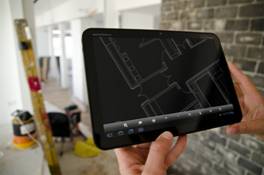
AutoCAD WS for Android enables an expanded group of users to enjoy the benefits of collaboration with architects, designers, and engineers from anywhere in the world and experience the freedom of taking designs with them.

Product users will experience a simplified, intuitive set of viewing, editing, and markup tools to work on designs while on the go. You can open drawings from email attachments, sync files from the web, or upload drawings directly from AutoCAD software through the integrated online tab. Drawings can also be saved locally for use in the field when an Internet connection is unavailable.

One feature is the text annotation tool that supports integrated voice commands available on devices running Android 2.2 (Froyo) or above. Now Android users can insert comments and notations on a drawing simply by speaking rather than typing them into the text edit box.

Additional feature enhancements that are available with this release include: 

  • Plot to PDF (web app only): Users can publish their DWG drawing to PDF using the free AutoCAD WS web application just as they would with AutoCAD software.
  • Anywhere Storage (web and mobile apps): In addition to the AutoCAD WS cloud, customers can now connect directly to alternate storage folders from their Android, iPad and iPhone devices, as well as through the AutoCAD WS web application. This currently includes: the Autodesk Buzzsaw service, Dropbox (through DropDAV), Microsoft SharePoint, Windows Server 2008, Box.net, MobileMe, and Egnyte, and other cloud storage providers who support the WebDAV protocol.


Availability: AutoCAD WS for Android will be available for download on the Android Market beginning April 20, 2011. Register and find out as soon as the download is available.


Autodesk

www.autodesk.com

Filed Under: 3D CAD Package Tips, Autocad Blogs, Autodesk, Autodesk News, CAD Hardware Tagged With: Android, AutoCAD, Autodesk, Buzzsaw

Dassault Systèmes’ DraftSight Now Available for Linux

March 9, 2011 By Laura Carrabine Leave a Comment

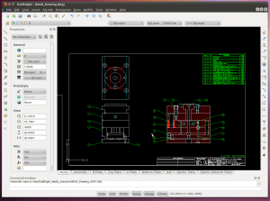
Dassault Systèmes (DS) announced the availability of a beta release of DraftSight for Linux.  DraftSight is a no-cost 2D CAD product for CAD professionals, students, and educators that can be downloaded at DraftSight.com.

DraftSight for Linux allows users to create, edit and view DWG files.  DraftSight generally takes a few minutes to download and runs on multiple operating systems, including Linux and Mac OS in beta, and Windows XP, Windows Vista and Windows 7 in general release. 

DraftSight beta users have access to no-cost Community Support available within the DraftSight open, online SwYm community where they can access support and training resources, along with an environment to interact, ask questions and share their opinions.  The DraftSight community is one of the first social networks designed by engineers for engineers, designers, and architects. 

Dassault Systemes

www.3ds.com

Filed Under: 3D CAD Package Tips, CAD Blogs, CAD Hardware, CAD Package Tagged With: Dassault Systemes, DraftSight, DWG, Linux

Designing Formula One sophistication with Bunkspeed SHOT Pro

February 24, 2011 By Laura Carrabine Leave a Comment

Cosmic Motors’ Daniel Simon is an internationally acclaimed concept designer and automotive futurist who’s worked with some of the world’s most prestigious automobile makers including Bugatti and Lamborghini. Simon is also the concept vehicle designer behind Disney’s 2010 blockbuster sci-fi flick, “Tron: Legacy,” and lead vehicle designer of Marvel’s highly anticipated 2011 summer release “Captain America.”

In early 2011, Simon added Formula One (F1) racecar designer to his resume, with the world debut of Hispania Racing’s (HRT) F111 car. As HRT enters its second season in the most competitive motorsport on Earth, they reached out to Simon to create strong and iconic livery for their 2011 car.

The first thing Simon tackled was to divide the car graphically into attractive red sponsors areas, and zones of freedom — the latter being distorted shapes where no sponsor sticker works. For the sponsor areas, there are many rules – F1 is one of the most expansive marketing fields in sports. Then, Simon filled the free zone with checkered flags and large racing numbers – “a playful, almost retro-romantic racing approach that I missed in this very serious sport,” claims Simon. The last touch was adding little humorous warning messages to resemble the look of modern aircraft. The reaction from the team and fans, when the F111 car was unveiled was overwhelming.

To turn the massive production CAD data of the F1 car into photo real images overnight for the season premiere, Simon relied on Bunkspeed SHOT Pro 3D rendering software running on NVIDIA Quadro 6000 professional graphics solutions.

“I had less than a day to render the complete press package for the global launch of the HRT F111 – which included 16 images at 5K resolution – there was no room for failure,” continues Simon. “With Bunkspeed SHOT Pro running on NVIDIA Quadro 6000 GPUs I was able to make the impossible happen, and complete the project in roughly 6.5 hours. It would have taken me twice as long if I used a traditional rendering solution running on CPUs.”

Bunkspeed

www.bunkspeed.com

NVIDIA

www. nvidia.com

Filed Under: 3D CAD Package Tips, CAD Hardware Tagged With: 3D, Bunkspeed Shot Pro, Cosmic Motors, Formula 1 CAD, NVIDIA

Screaming workstation

February 17, 2011 By Laura Carrabine Leave a Comment

The BOXX 8550 Xtreme is a dual processor workstation well suited for design visualization specialists or CAD/CAE software users who need a system to perform multiple simulations or toolpath calculations at the same time.

A test machine featured two Intel Xeon X5680 processors, but instead of the 3.33GHz clock speed they usually run at, both chips have been overclocked to an 4.2GHz. Naturally, this creates a lot of heat and a sophisticated liquid cooled sub-system is used to keep them running within their thermal limits.

The result of having two Xeon chips run at such speeds is an exceptionally fast workstation. It recorded the fastest ever time our 3ds Max benchmark, using its 12 physical and 12 virtual HyperThreading cores to full effect, rendering the test scene in 96 seconds.

It also made light work of our PowerMill CAM test, setting new records when running two and three tests concurrently.

The BOXX 8550 Xtreme is also well equipped in the graphics department. The 2GB Quadro 4000, one of Nvidia’s high-end Fermi graphics cards, recorded impressive results in our SolidWorks graphics test.

Storage is a little underwhelming for a machine of this caliber, comprising one 160GB 2.5” 7,200RPM SATA hard drive for operating system and applications and a 500GB drive for storage.

However, optional Solid State Drives (SSDs) are also available in sizes of 60GB – 256GB. All drives are tucked behind the motherboard.

BOXX Technologies

www.boxxtech.com

Filed Under: 3D CAD Package Tips, CAD Blogs, CAD Hardware, SolidWorks Tagged With: 3D, Boxx, cad, CAE, Intel, Power Mill CAM, Xeon

CAM – Face classification

July 13, 2010 By Laura Carrabine Leave a Comment

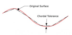
To explain the principle, if you simply break a 3D curve into equal length lines, the deviation of the lines from the curve would change as the curvature became larger and smaller. However, using a chordal deviation, the operator defines the maximum distance between the chord and the original geometry. The major benefit of using a chordal deviation to control the 3D mesh is that you have a consistent, predictable deviation.

You may then ask why not a set of very small chordal tolerance? In theory you can but this does effect the data size and also produces extra CNC code when it may not be necessary. You also have to be aware that on older machines without high speed controllers, the extra movements could choke the machine if the feed rates are not reduced. Dropping the feed rate is non-productive and reducing the accuracy means more time polishing and a less accurate part.

Okay, with the problem explained, the following tip shows how it is possible to improve this situation by defining a different set of chordal parameters based on face type.

When defining the piece parameters, the general chordal tolerance and angular tolerance is applied to the complete model. However, there is a face classification box that open an additional set of parameters that separates the tolerances for planar and radiused faces.

If the face classification box is NOT active, the general tolerances are applied to the complete model.

If the face classification box IS active, additional tolerance parameters become active. This allows the operator to separate the model into 3 tolerance bands – planar faces, radiused faces, and the general faces.

The major advantage of the mesh optimization is that it allows the operator to be more creative with the machining tolerances and still retain a sensible model size.

If you use the face classification option within the piece definition, it is then possible to graphically display and sort by face type when displaying the mesh within the piece manager. Even at this point within the tree structure, it is possible to select an individual face and define a different chordal and angular tolerance. If individual face parameters are applied, the face will be displayed with a different icon within the tree.

Vero Software
www.vero-software.com

Filed Under: 3D CAD Package Tips, CAD Hardware Tagged With: 3D, cam, chordal, CNC, Vero Software

3Dconnexion Mice Offer Advanced Design Control in Missler TopSolid

January 22, 2010 By 3DCAD Editor Leave a Comment

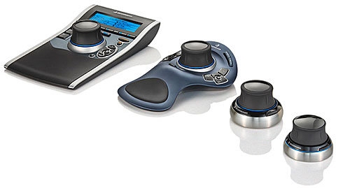
3Dconnexion’s 3D mice give TopSolid 7 engineers increased productivity and an intuitive way to interact with 3D designs for modeling, simulation, and production.

–3Dconnexion’s 3D mice provide TopSolid 7 professionals with a range of design performance and productivity benefits, including:

–Improved Control and Navigation allow you to simultaneously pan, zoom, and rotate models or simulations without stopping to select commands.

–Greater productivity with customizable programmable buttons that provide quick access to commonly used TopSolid 7 commands.

–Advanced design performance by aiding in the detection of design flaws and enhancing design review, verification, and presentation.

–Reduce mouse clicks by 50%.

3Dconnexion
www.3Dconnexion.com

Missler Topsolid
www.topsolid.com

::Design World::

Source: :: Design World ::

Filed Under: CAD Hardware, Featured

  • « Go to Previous Page
  • Go to page 1
  • Go to page 2
  • Go to page 3

Primary Sidebar

3D CAD NEWSLETTERS

MakePartsFast

Footer

3D CAD World logo

DESIGN WORLD NETWORK

Design World Online
The Robot Report
Coupling Tips
Motion Control Tips
Linear Motion Tips
Bearing Tips

3D CAD WORLD

  • Subscribe to our newsletter
  • Advertise with us
  • Contact us
Follow us on Twitter Add us on Facebook Add us on LinkedIn Add us on Instagram Add us on YouTube

3D CAD World - Copyright © 2022 · WTWH Media LLC and its licensors. All rights reserved.
The material on this site may not be reproduced, distributed, transmitted, cached or otherwise used, except with the prior written permission of WTWH Media.

Privacy Policy