• Skip to primary navigation
  • Skip to main content
  • Skip to primary sidebar
  • Skip to footer

3D CAD World

Over 50,000 3D CAD Tips & Tutorials. 3D CAD News by applications and CAD industry news.

  • 3D CAD Package Tips
    • Alibre
    • Autodesk
    • Catia
    • Creo
    • Inventor
    • Onshape
    • Pro/Engineer
    • Siemens PLM
    • SolidWorks
    • SpaceClaim
  • CAD Hardware
  • CAD Industry News
    • Company News
      • Autodesk News
      • Catia News & Events
      • PTC News
      • Siemens PLM & Events
      • SolidWorks News & Events
      • SpaceClaim News
    • Rapid Prototyping
    • Simulation Software
  • Prototype Parts
  • User Forums
    • MCAD Central
    • 3D CAD Forums
    • Engineering Exchange
  • CAD Resources
    • 3D CAD Models
  • Videos

Siemens PLM & Events

Altium Takes Native 3D PCB To a New Level of ECAD and MCAD Integration

August 8, 2013 By Stacy Combest Leave a Comment

Altium Limited has partnered with Desktop EDA to provide designers with advanced ECAD and MCAD integration. The new add-on application, Desktop EDA Solidworks Modeler and the IDF Modelers, is currently available for Altium Designer.

The extension apps for Altium Designer and their companion plug-ins form a bridge between the ECAD and MCAD design worlds. Productivity is greatly increased through the full synchronization capabilities between the target applications. This goes much further than simply eliminating the requirement to recreate MCAD assemblies each time, allowing the modeling of Altium Designer-specific features in the target MCAD system.

MCAD

SolidWorks Modeler for Altium Designer
By transferring data directly between Altium Designer and SolidWorks programs running on the same PC, designers need not use intermediate files to synchronize design changes and facilitate engineering change orders (ECO). This approach eliminates translation issues, saves time and provides a more detailed model of the PCB design in SolidWorks.

By including PCB copper layers in the transfer, the design in SolidWorks can then be used as a starting point for more advanced mechanical CAD operations, such as thermal simulation.

IDF Modeler for Altium Designer
Desktop EDA’s advanced IDF modeler app for Altium Designer allows users of the native 3D PCB design system to export and import a rich, complete model of the 3D PCB in the industry standard IDF file format. Coupled with a companion Desktop EDA plug-in for the target MCAD design tool, teams save time by having a both full synchronization features as well as PCB copper design elements.

Companion Plug-ins are also available for Dassault SolidWorks, Autodesk Inventor, and Siemens Solid Edge.

Desktop EDA apps for Altium Designer are available through Altium Sales channels. More information can be found at

http://altium.com/en/partners/apps/solidworks-modeler

http://altium.com/en/partners/apps/idf-modeler

To learn more about Altium’s unique, native 3D PCB design system, visit: http://altium.com/en/solutions/ecad-meets-mcad

Altium
www.altium.com


Filed Under: Autodesk News, CAD Package, Dassault Systemes, Siemens PLM & Events Tagged With: Altium

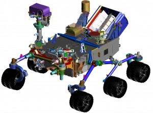
How was the Mars rover Curiosity designed? With Siemens PLM software

August 7, 2012 By Evan Yares Leave a Comment

Last Sunday night, I watched the live video feed from NASA’s Jet Propulsion Laboratory, as the rover Curiosity descended through the Martian atmosphere, and landed on the planet’s surface.

NASA called the process of landing the Curiosity “7 minutes of terror.” The whole process was completely automated—and all that the people at JPL (or the tens of thousands of us who were watching over the web) could do was wait, helplessly, as the drama played out. When Curiosity landed safely, and sent its first pictures from Mars’ surface, cheers rang out—not just at JPL, but on Twitter and other social media sites.

One of the things I noticed immediately, when I tuned into www.nasa.gov was that the average age of the scientists and engineers shown in the feed was quite young. I’d noticed this before, in a video segment shot by PhD Comics inside the Mars Rover Test lab, where NASA engineers Chaz Morantz and Bobak Ferdowski talked about Curiosity.

It’s not your father’s NASA anymore.

The Curiosity is the largest and most advanced space exploration robot ever made. It was designed with Siemens PLM software, including TeamCenter and NX, and is almost a best-in class example using those to tools, from conceptual design, to full-system simulation. (To understand why I say “almost,” keep reading.)

Here are a few videos that discuss Siemens PLM’s involvement with the Curiosity rover project:

Here is Daren Rhoades, who works for Siemens PLM, and used to work for JPL, explaining some of the challenges in designing Curiosity:

Doug McCuiston, Director of the Mars Exploration Program, talking about the importance of Siemens PLM software in designing Curiosity:

You can watch these, and other videos here.

Almost a best-in-class example.

In the videos, NASA’s Doug McCuiston says: “The challenges of building something like that, with all the parts that are involved—all the discrete parts, all the interfaces, and all the testing, and the ability to maintain not just the documentation, but all the drawings, the test flows, the verification items, is a very complex task in itself.”

No kidding.

Yet, if NASA were to design Curiosity today, I suspect they’d want to take a serious look at a couple of advancements in Siemens PLM software could make their life quite a bit easier.

Active Workspace

The first is a product called Active Workspace. Siemens calls it “a personal environment for accessing your entire PLM system.” You can download a fact sheet for it here.

I was lucky enough to be able to Active Workspace before its public announcement, and talk to some of the key people behind its development. The product includes a lot of really valuable capabilities, incluidng product data navigation and visualization, visual reporting, shared contexts, flexible collaboration, and ridiculously powerful search (including shape search.)

But what completely surprised me was that it goes way beyond just letting you view relationships between parts. It lets you view relationships between all of your product information, including requirements, functions, logical diagrams, and systems-engineering information.

Let me put that in a different way: Active Workpace supports a systems engineering driven product development process. It is systems engineering that lets you link together all the disparate elements of a product design into an intelligent product model, which can be continuously validated. It is the key to enabling true model-based development.

Here’s Chuck Grindstaff, CEO of Siemens PLM Software, talking about systems engineering and Active Workspace:

Product and Manufacturing Information

The other advancement from Siemens PLM that NASA would benefit from isn’t entirely new, but it’s become increasingly important: PMI (Product and Manufacturing Information.)

If you watch the videos about Curiosity, you’ll notice that they talk about “drawings.” CAD drawings have been around a long time—but that doesn’t mean they’re a good thing. They’re designed for human interpretation, and are thus subject to human misinterpretation. And they create a disconnect between product design and manufacturing.

PMI can contain GD&T, weld symbols, text and dimensions, as well as the product definition and process notes. PMI can exist in 3D models in the same way that information exists on 2D drawings – using leader lines that connect the data to specific parts in the product design.

The use of PMI shortens the design cycle by enabling product teams to incorporate product and process information during the design phase. This results in better communication between design and manufacturing groups, fewer errors, streamlined design and manufacturing processes and faster change management. PMI not only reduces the need to generate 2D drawings; it also enables downstream applications to directly access this information for automating tasks such as CNC programming, tolerance stack up analysis and CMM analysis.

Here’s what Norm Crawford, of Applied Geometrics, has to say about PMI: “Through the use of 3D documentation methods (i.e., PMI), the time and cost of documenting a part can be reduced by 50 percent and make early involvement of manufacturing easier with state of the art online 3D collaboration and visualization tools. Limiting redundant annotation and views – normally created on drawings in an attempt to clarify part design requirements – leads to better communications with fewer interruption errors, improved first time quality and increased productivity.”

You can watch a video about NX PMI here.

Now, as for NASA: they may well be using PMI already. NX has supported PMI for many years. If they produced 2D drawings for the Curiosity rover, it may have been a crutch (because of some immaturity in NX’s support for PMI at the time), or it may have been just a matter of habit. (CAD people love their drawings, and don’t want to give them up.) In either case, today’s NX supports PMI well enough that there’s no reason to create 2D drawings. And many reasons not to.


Filed Under: Evan Yares, Siemens PLM, Siemens PLM & Events Tagged With: Siemens PLM

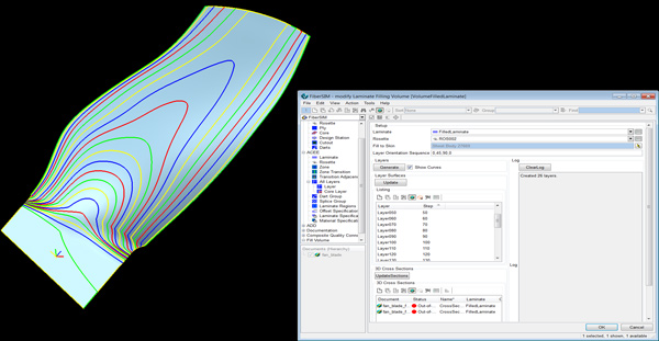
Now that Siemens PLM has acquired Vistagy, will Dassault Systemes play nice?

May 10, 2012 By Evan Yares 6 Comments

You may know that Siemens PLM recently acquired Vistagy, whose Fibersim software has been used to design 80% of the composites currently flying in today’s aircraft.

Vistagy has been a long-term third-party partner not just to Siemens PLM, but also to Dassault Systemes. Though DS has its own composite design solution, many of its most important customers use Fibersim. To say Vistagy has been an important partner for DS would be an understatement.

Siemens PLM Vistagy Fibersim

My interest in Vistagy is as a microcosm of the relationship between Siemens PLM and Dassault Systemes. Let’s face it: These two companies are serious competitors. Has Siemens acquisition of Vistagy upset a tenuous détente (if it can even be called that) between these two giants of PLM?

This week at Siemens PLM Connection, I got a chance to speak with Steve Luby, the current Sr. VP of Siemens’ Specialized Engineering Software business segment, and former CEO of Vistagy. He told me that he’d always been careful in maintaining Vistagy’s relationship with DS. Since Vistagy had been a long-term partner to both DS and Siemens PLM, he got used to treading carefully. Since the Siemens acquisition, Luby explained, DS has not done anything precipitous (such as tossing Vistagy/Siemens out of their partner program.)

But that’s not surprising. Doing that would be the equivalent of mutually assured destruction. It’d be tough to explain to the biggest aerospace firms in the world that, oops, they can’t use Vistagy’s products anymore.

My guess, though, is that DS is focusing big energy on improving their composite solution (which I understand is mighty competent already), with the eye to displacing as many seats of Fibersim as they can. Yet, even in the best of all worlds, that’s going to be hard to do. I can’t imagine Boeing, for example, dropping Fibersim from the toolset used on the 787 Dreamliner—a plane that’s 50% composites by weight.

I don’t anticipate that DS is going to open their doors, and let Siemens/Vistagy have completely unfettered access to their APIs (and customers!) The current Vistagy products, including applications for composites, airframe fasteners, and automotive/aerospace seating, are probably grandfathered in. But future Specialized Engineering (i.e., Vistagy) products?

It’s a big wild-card. The new Codex of PLM Openness that both DS and Siemens recently signed would suggest that the companies are going to play nicer together than they have in the past. Yet, my reading of the Codex is that it gives an awful lot of wiggle room.

The Siemens Vistagy acquisition presents a nice public context for DS to show that they’re committed to openness. To playing (competing) nice. If my reading between the lines is right, the situation is “so far, so good.” If you’re a Vistagy customer, and you hear anything different (good or bad), I’d sure like to hear about it.

Filed Under: Catia, Dassault Systemes, Evan Yares, Featured, Siemens PLM, Siemens PLM & Events Tagged With: Dassault Systems, fibersim, Siemens PLM, vistagy

Why CAD is hard: Geometric problems

May 8, 2012 By Evan Yares 4 Comments

Imagine you were a CAD programmer (if you actually are one, play along with me here.) What problems would you focus your energies on?

From my perspective, persistent bugs and software stability would be a good primary focus. But, let’s limit it to geometric modeling problems. Not just the run of the mill “fix this bug” stuff, but rather the real serious problems.

George Allen, Chief Technologist & Technical Fellow at Siemens PLM Software, wrote an interesting paper for an academic conference, where he talked about what he saw as the big geometric modeling problems in industrial CAD/CAM/CAE software. You can download a copy of the paper at this link.

In short, Allen sees three particularly tough problem areas: filleting, history-based models, and performance.

Consider filleting: According to Allen, “the filleting problem is important because it consumes a great deal of modeling time – typically as much as 40% in parts like castings, forgings, and sheet metal stampings.” He points out “the filleting functions in CAD systems are often unpredictable, counter-intuitive, and prone to failure. So, producing the desired results often requires considerable user skill, which means that the task can not be done effectively by low-priced inexperienced workers.”

The problem with history-based models starts when the replay (or rebuild) process fail—which often happens if parameters (or inputs) are changed substantially from previous ones. “When this happens, the user must ‘debug’ the model. He has to understand the sequence of steps that was used to build it, and find out which of these steps are failing, and why. The process is very similar to the debugging of programs — in fact, in a sense, a history-based model is a program. But, unfortunately, the debugging tools are very primitive compared to those available for debugging programs. As a result, people often just give up and rebuild the model from scratch.”

Allen sees two distinct problems in performance. First is with large models: “Our users are dealing with enormous models. A motor vehicle, for example, will typically have around 30,000 parts, and overall data size is likely to be around 15 or 20 gigabytes. The largest parts are complex castings like the engine block and complex sheet metal parts like the floor pan.” The second problem is less obvious; “that some operations take a few seconds, but users really need the computations to be done in real time (in other words, in around 1/30th of a second). Lack of real-time response makes some exploratory functions unusable, and this impairs user creativity.”

How much performance improvement would be enough? Allen says that “in either case, we need performance that is roughly 100x better than we have today, so clearly small incremental refinements of our current approaches will not be sufficient.”

In the paper, Allen suggests some possible solutions to these problems, but he really leaves things pretty open. The paper was targeted at academic researchers, to point them in the direction of research that would be of real value to developers of commercial CAD/CAM/CAE software—and ultimately, their customers.

Take a few minutes to download and read the paper. You’ll come away with a greater understanding of how challenging it can be to create good CAD software.


Filed Under: Evan Yares, Featured, Siemens PLM & Events Tagged With: cad, Geometric Modeling, George Allen, Siemens PLM

Siemens PLM Software is General Motors Supplier of the Year, for the fourth time

April 12, 2012 By Evan Yares Leave a Comment

You may be surprised to learn this, but there are a lot of companies that are not particularly happy with their CAD and PLM suppliers.  It has a lot to do with over-promising and under-delivering.

For Siemens PLM Software to win GM’s Supplier of the Year award for the fourth time is really something.  The award is given based on ratings for quality, service, technology, and price.  It’s not something that a supplier can get by playing golf with the chairman.

The people at Siemens PLM should be justifiably proud of this honor.  Then, they should take a big breath, and get back to work, because millions of engineers are counting on them for the tools to help them get their jobs done better.

The official Siemens press release follows:

Siemens PLM Software Receives General Motors Supplier of the Year Award for the Fourth Time

GM Supplier of the Year Award for IT Builds on Siemens PLM Software’s Strong Momentum in the Global Auto Industry

“We Look Forward to Continuing to Contribute to the Remarkable Resurgence and Excitement of the new GM,” says CEO, Chuck Grindstaff

DETROIT, April 10, 2012 – Siemens PLM Software today announced it has received the prestigious 2011 General Motors Supplier of the Year Award at a ceremony held March 13th at the Detroit Institute of Arts. GM cited the important role that Siemens PLM Software has played in the automaker’s efforts to design, build and sell the world’s best vehicles. This is the fourth time the global supplier of product lifecycle management (PLM) software has won this award, which rates suppliers in a variety of categories including quality, service, technology, and price.

“Siemens PLM Software’s partnership, and dedication to consistently perform above expectations, contributed to both our companies’ success,” said GM executive, Timothy Cox. “The entire GM team appreciates the efforts of the Siemens PLM Software team and wants to recognize the entire organization for its performance.”

“After working so closely with the incredible team at GM to thoroughly understand their requirements and deliver the solutions they need to build some of the world’s best cars and trucks, it is particularly gratifying to be named a 2011 General Motors Supplier of the Year,” said Chuck Grindstaff, CEO and president, Siemens PLM Software. “We know that understanding our customers and the industries they serve has helped us formulate a unique and practical vision for PLM that has contributed to the unmatched growth and momentum we are experiencing in the global automotive industry. So we want to thank General Motors for this award and for their partnership. We are truly honored to have been selected from such a prestigious list of IT suppliers, and we look forward to continuing to contribute to the remarkable resurgence and excitement of the new GM.”

Siemens PLM Software supplies General Motors with a comprehensive set of integrated software, services and expertise to help automate their entire product lifecycle process. The offerings in use at GM include, but are not limited to, NX™ software for computer-aided design, manufacturing and engineering analysis, Teamcenter® software for digital lifecycle management, andTecnomatix® software for digital manufacturing automation and simulation.

Broad automotive leadership, unmatched momentum
Siemens PLM Software has experienced unmatched momentum and established a broad leadership position in the global automotive industry by adding several prominent automotive original equipment manufacturers (OEMs) and suppliers to its customer base over the past several years. Its technology is now used throughout product development and manufacturing by more than 90 percent of the world’s top 15 automotive OEMs and nearly 90 percent of the top 25 Tier One auto suppliers. In fact, Siemens PLM Software technology is used in the development of more than 80 percent of all the vehicles produced worldwide by all 47 of the world’s top OEMs ranked by the International Organization of Motor Vehicle Manufacturers (OICA).

About Siemens PLM Software
Siemens PLM Software, a business unit of the Siemens Industry Automation Division, is a leading global provider of product lifecycle management (PLM) software and services with 7 million licensed seats and more than 71,000 customers worldwide. Headquartered in Plano, Texas, Siemens PLM Software works collaboratively with companies, delivering open solutions to help them make smarter decisions that result in better products. For more information on Siemens PLM Software products and services, visit www.siemens.com/plm.

About the Siemens Industry Automation Division
The Siemens Industry Automation Division (Nuremberg, Germany) supports the entire value chain of its industrial customers – from product design to production and services – with an unmatched combination of automation technology, industrial control technology, and industrial software. With its software solutions, the Division can shorten the time-to-market of new products by up to 50 percent. Industry Automation comprises five Business Units: Industrial Automation Systems, Control Components and Systems Engineering, Sensors and Communications, Siemens PLM Software, and Water Technologies. For more information, visit www.siemens.com/industryautomation

Note: Siemens and the Siemens logo are registered trademarks of Siemens AG. NX, Tecnomatix and Teamcenter are trademarks or registered trademarks of Siemens Product Lifecycle Management Software Inc. or its subsidiaries in the United States and in other countries. All other trademarks, registered trademarks or service marks belong to their respective holders.

Filed Under: Evan Yares, Featured, Siemens PLM & Events Tagged With: General Motors, GM, Siemens PLM

Active Workspace: Big news for Teamcenter users

April 6, 2012 By Evan Yares 3 Comments

Siemens PLM just announced Active Workspace, a new product in the Teamcenter software portfolio.

There are three general groups of people who are going to be interested in Active Workspace: those who use Teamcenter, those who’ve thought about adopting Teamcenter, but haven’t made the jump yet, and those who are using competing PLM solutions, who will likely be telling their suppliers “we want something like this.”

Siemens PLM describes Active Workspace as “a personalized environment for accessing the entire PLM ecosystem, which provides all PLM users with the right information at the right time to make the right decisions. Active Workspace delivers high-performance search and visualization capabilities, simple yet powerful collaboration tools, and a groundbreaking user interface. Active Workspace delivers the multi-disciplinary decision support platform that PLM workers need to make smarter decisions and better products.”

So, Active Workspace connects users to the resources (people and information) they need to get their jobs done better.

Siemens PLM Software CEO Chuck Grindstaff puts it this way: “All companies and individuals face the challenge of dealing with information overload due to the increasing speed and volume of data coming from multiple sources. Active Workspace helps companies manage this challenge and significantly enhances decision making by reducing complexity and intelligently presenting PLM information that is accessible for all users… Active Workspace creates an intuitive and personalized 3D graphic interface that significantly enhances the ability of our PLM suite of offerings to deliver knowledge instantly to the right people, at the right place and in the right context to support rapid and intelligent decision making.”

Like I said, it connects users to the resources they need to get their jobs done better.

Joe Barkai, the Practice Director for Product Lifesyle Strategies at IDC, explains it a bit differently: “The constant increase in product complexity creates a need for a strong multi-disciplinary decision support platform that makes information exchange and collaboration simple, intuitive and effective. A dynamic decision support system, like Active Workspace, creates rich technical and business context to enable intelligent, high-fidelity decision making.”

Like I said, it connects users to the resources they need to get their jobs done better.

You might call Active Workspace a “dashboard.” It’s the place where a user will come to at the beginning of their work day. Here are Active Workspace’s major features:

Visualize and Navigate Product Data

  • Allow users to easily locate, browse and visualize products in greater detail using intuitive graphical controls.
  • New high-performance visualization capabilities allow users to view products in a fraction of the time previously required.
  • Intuitively see and understand how data relates to the network of information that supports and defines it, helping users make timely, high-quality decisions.

Compare and Report Product Information

  • Easily investigate rich PLM information directly on the 3D product model with color-coded, easy-to-understand, visual reports.
  • Create visual reports without the need for training or support from IT.

Configure and Share Contexts

  • Save the recipe for decision contexts by utilizing our innovative new shelf.
  • Share information with another user or a whole group of users − whether it is a filtered list of search results, a color-coded visual report, or anything else – by dropping it on the shelf.
  • Once something is on the shelf, anybody else with access can reference the data, confident that the information is accurate and current.

Collaborate Effectively

  • Active Workspace will proactively suggest appropriate people for users to collaborate with based upon the context of the information they are reviewing, helping make sure they engage the right people to assist in making the right decision.
  • Collaboration tools are seamlessly integrated into Active Workspace, keeping users in a single tool and allowing them to get the answers they need faster.
  • Active Workspace integrates with e-mail and instant messaging, as well as Teamcenter Application Sharing, providing numerous ways to share information.

Find What You Need Faster

  • Return search results faster than ever before, bringing information to the user almost instantly.
  • Enable users to find and access information from anywhere in their PLM ecosystem, not just information managed by Siemens PLM Software products.
  • Intuitive filtering allows users to quickly narrow search results down to just the information they require without having to know a lot about that data beforehand.
  • Embedded shape search capabilities allows users to find components that are geometrically similar.

Here are some images that show screen shots from Active Workspace.  Click on the images to see high-resolution versions of the images.

Active Workspace suggests key stake holders for a user to collaborate with on this product.

An Active Workspace user views the product in intuitive 3D and sees the relationships to other information at the same time.

A user views high performance, realistic graphics in Active Workspace.

Systems Engineering relationships are clearly displayed in Active Workspace.

A user views a color coded graphical report directly on the 3D product model in Active Workspace.

Search results from multiple sources are clearly displayed to the user in Active Workspace.

Why is Active Workspace a big deal?

What Active Workspace isn’t is a shiny front-end pasted on a PLM system, just to make it look sexier.  It is a serious tool to help engineers to get their work done faster and better when dealing with information overload and organizational complexity.  It’s just what a good tool should be: a force multiplier.


Siemens PLM Software 


Filed Under: Evan Yares, Featured, Siemens PLM, Siemens PLM & Events Tagged With: Active Workspace, Siemens PLM, Teamcenter

Should you buy your CAD software—or rent?

February 2, 2012 By Evan Yares 4 Comments

CAD software isn’t cheap. A mainstream 3D CAD program will set you back thousands of dollars upfront, and a bunch more in annual maintenance charges.

The cost can be daunting. But what if there was a way to spread it out, and pay as you go?

Rental: An idea that’s been tried.

A dozen years or so ago, a relatively new CAD vendor, Think3, started offering their CAD software on a monthly rental basis. It was an intriguing idea, but it would have worked better had Think3’s software been more mature at the time. People tend not to renew rentals when the software doesn’t do what they need.

More recently, Ashlar-Vellum has offered their line of CAD programs under a number of licenses, including permanent, one-year, and monthly rental. Though Ashlar’s software is highly respected (especially by industrial designers), the company isn’t one of the big players in the CAD business.

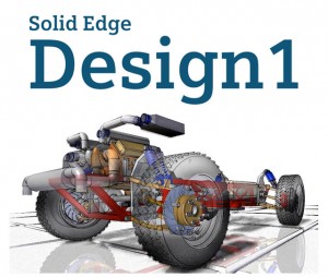
Solid Edge Design 1Recently, Siemens PLM, which is one of the big players, revisited the idea of renting CAD software—but with a new twist. They partnered with Local Motors, a company that does crowd-sourced design of cars. Members of the Local Motors community can rent (actually “subscribe,” but with enough flexibility that it seems like renting) a special version of Solid Edge called Design 1, for $19.95 per month.

Solid Edge Design 1 is a capable CAD program, incorporating Siemens’ Synchronous Technology direct modeling tools. It’s no toy.

There are a couple of key things that make this initiative interesting. First, Solid Edge Design 1 is capable of effectively importing and editing solid models imported from most common CAD systems, including SolidWorks and Pro/E. Second, Design 1 is a direct modeler (it doesn’t include history-based modeling), so it’s quite a bit easier for a normal person (as opposed to a CAD guru) to get up and running on than systems such as SolidWorks and Pro/E (or, for that matter, the full-blown version of Solid Edge.)

Simplicity can be compelling: Solid Edge Design 1 can work with the data you have, doesn’t take a whole lot of time to learn to use, and only costs 20 bucks a month, with no long-term commitment.

One good question might be why Siemens PLM is offering Design 1 through Local Motors, instead of directly. It’s probably because Jay Rogers, Local Motors’ CEO, came to Siemens PLM, and said “this is what we’re looking for.” Siemens PLM responded, saying “that sounds interesting. Let’s give it a try.”

The only real “catch” with Solid Edge Design 1 is that it’s really only intended to be used for Local Motors related projects. Its native CAD files can not be read by the commercial versions of Solid Edge (though, because it is a direct modeler, it can write perfectly good neutral files, such as IGES, STEP, and JT.)

Siemens PLM has recently gone beyond just offering a $20 per month version of Solid Edge to the Local Motors community. They’re now offering the full-range of Solid Edge versions, up to Solid Edge Premium, with full FEA simulation, wire harness design, pipe and tube routing, for rental prices ranging from $99.00 to $299.00 per month. These versions of the software can technical support from Siemens.

At first blush, $300 a month sounds like a lot of money. It might be, for a hobbyist who just wants some CAD software to play at designing cars. But, for a person who plans to use the tool for serious work, it’s not that much. Put it in context: A commercial license of Solid Edge Premium sells for on the order of $7,500 up-front, plus another $2,000 or so in annual maintenance fees.

To me, $300 per month for this software, including updates and direct support, seems like a bargain.

For small to medium size businesses, the ability to pay for software as an expense, rather than as a capital item, is pretty compelling. Even more compelling is the ability to control costs by adding or reducing CAD seats as needed.

Is software rental the wave of the future?

Software rental has three problems that CAD vendors don’t like: First, the revenue stream has to be recognized for accounting purposes as it comes in, rather than upfront. For publicly held corporations focused on reporting lots of revenue, that’s not very attractive. Second, it’s hard to pay front-loaded commissions and bonuses to salespeople on rentals. And third, there’s no guarantee that someone who is renting software will continue to do so. That is, it’s difficult to “lock-in” those customers (and their revenue) over the long term.

Siemens PLM could get away with this initiative for a few reasons: They limited it to Local Motors community members, so they can learn what works (and what doesn’t) without messing with their entire customer base. As Solid Edge is not the market sales leader, they’re more likely to displace competitive seats than their own. Since the Solid Edge product group is only a tiny part of the giant Siemens corporation, there’s not much risk that this program’s success or failure will impact their next quarter’s financial results (and stock price.) And, finally, they have enough confidence in their product to believe that a pretty reasonable percentage of the people who have a chance to use it will like it.

While the Siemens PLM/Local Motors partnership is probably a bit of an experiment, it’s encouraging. Anything that can make good CAD tools more affordable is likely to be popular with users.

Siemens PLM Systems

http://www.plm.automation.siemens.com

Local Motors

http://forge.local-motors.com


Filed Under: Evan Yares, Siemens PLM, Siemens PLM & Events Tagged With: 3D CAD, Licensing, Local Motors, Siemens PLM, Solid Edge

Fast design process supports rapid growth

January 11, 2012 By Laura Carrabine Leave a Comment

As its name implies, Giant KONE Elevator Co., Ltd., is big in the elevator industry. Founded in 1910 in Finland, the company has become one of the world’s largest elevator and escalator manufacturers. KONE first entered the Chinese market in 1996. KONE entered into a joint venture agreement with Zhejiang Giant Elevator Co., Ltd., the leading Chinese elevator manufacturer.

The company’s product line includes escalators, moving sidewalks, passenger elevators, sightseeing elevators, and freight elevators. These are produced on some of the most advanced manufacturing equipment in China, including a Salvagnini fully automatic flexible sheet metal production line. Major projects in China include the National Centre for the Performing Arts, Capital Airport and the National Stadium (the Bird’s Nest).

Elevators are electromechanical systems that must fit perfectly into the customer’s building; they are shipped as bulk components and installed at the customer’s site. Thus, most projects are one-off. Management set a goal of standardizing portions of the design process as a way of boosting productivity.

Another factor that previously hampered productivity was the use of multiple CAD programs that could not communicate with each other. “Giant KONE boasts a large number of designers of different ages and different levels of expertise, and their design software varied widely,” says Li Yong of the company’s Information Management department. “Problems were often encountered in upstream and downstream communications and as drawings were modified.” The company also lacked a comprehensive digital solution for managing its operations and product data.

Giant KONE’s original CAD software was 2D, which was adequate when the company had fewer orders, but as the workload grew, the drawbacks became evident. “Sometimes, a design had to be started again from scratch, just to make a simple 5-millimeter change in the dimension of a part,” says Yong. When designing new parts, designers made physical models first, then made drawings based on the models, made a round of physical prototypes from the drawings, and then verified the prototypes.

The chance to make a significant change to the design process came during a project done in conjunction with the National High Technology Research and Development Program 863. Called “Study of the Configuration Management Technology of Large Batch Customized Products and Its Application in the Elevator Industry,” this project was Giant KONE’s impetus to upgrade the design process from 2D to 3D. After investigating and testing a number of 3D solutions, Giant KONE chose Solid Edge software with synchronous technology from Siemens PLM Software. It hired United Digital Systems, Co. (UDS), a Siemens PLM Software platinum partner, to handle the implementation.

“Since implementing Solid Edge, Giant KONE has witnessed remarkable improvements in efficiency,” says Yong. With more than 90% of all products and components now modeled in 3D, it is possible to simulate the assembly of an elevator in Solid Edge prior to manufacturing. Only 2 physical prototypes are now required, down from 5 or 6 in the past. Engineering drawings are more accurate, and they are quickly created from the solid geometry. The average research and development (R&D) cycle for a new product has dropped from a year to 9 to 11 months.

“In working with a variety of parts, components and assemblies during the R&D of a high-rise escalator, Solid Edge with synchronous technology enabled our designers to easily locate problem areas and quickly modify them.” says Yong. “Synchronous technology enables our designers to significantly increase their modeling efficiency.” He explains, “In the past, we got all parts and components ready before assembly. Now, using synchronous technology, we work in a top-down way – first concept design, then accurate design and finally standardization.”

According to Yong, Solid Edge saves the company significant money. Solid Edge Simulation enables the company to improve its design verification process. Yong explains, “We’ve essentially eliminated physical prototypes. We now use Solid Edge for virtual assembly, dimensional simulation and interference checking, thus minimizing material waste and substantially reducing costs. Ultimately, using Solid Edge, we’ve saved ¥3 million.”

Yong adds, “The integration of Giant KONE’s Solid Edge design system with other applications has allowed the company to optimize our product design and manufacturing processes. Barriers between departments have been eliminated; information is immediately shared; and what you see is what you get in a design.”

Siemens PLM

www.plm.automation.siemens.com

Filed Under: 3D CAD Package Tips, CAD Blogs, CAD Package, Featured, Siemens Blogs, Siemens PLM, Siemens PLM & Events Tagged With: Giant Kone Elevator, Siemens PLM, Solid Edge

Boots for the boundary-free skier

January 11, 2012 By Laura Carrabine Leave a Comment

Black Diamond Equipment Ltd. makes equipment for climbing and skiing that regularly wins awards for its innovation and quality. Several years ago, Black Diamond decided to apply its expertise to a new area – free-ride ski boots. These boots are used in a certain niche of skiing known as “boundary-free” skiing. Boundary-free skiers strap their skis to a backpack, hike up a mountain (far from a conventional ski resort), and then ski down private slopes. Boundary-free skiers need the comfort and functionality of hiking boots for the climb up as well as the fit and performance of alpine ski boots for the ride down. The boots available at the time were so unsatisfactory that some skiers opted to use two pairs, carrying one pair in their pack so they’d have the right boot available when they needed it.

Black Diamond’s goal was to combine the two sets of performance criteria in one great-looking boot. “The other free-ride boots out there are made by European competitors with 50+ years of boot-making experience,” explains David Narajowski, director of advanced projects at Black Diamond. “Our challenge was not just to catch up to where they were, but to go beyond and create something much better.”

Black Diamond is a long-time user of CAD and has used its original design software, I-deas, from Siemens PLM Software, to develop many of its successful products. At the time the boot project started, however, the company had decided to standardize on the NX digital product development system, also from Siemens, an advanced design solution that still allows the company to leverage its legacy I-deas data. “Black Diamond’s design engineering centers worldwide have moved from I-deas and other CAD systems to standardize on NX,” Narajowski says. He notes, “Between I-deas and NX, there was a period of time when we tried a mid-range CAD program. But there is no way we could have developed a free-ride boot in a mid-range system.”

One of NX’s main advantages, according to Narajowski, is that it provides both the freeform modeling capability needed to capture the company’s design expertise (through the NX Shape Studio application, offered as part of the NX Mach III industrial design solution) as well as the powerful product design tools needed to turn an idea into a manufacturable product. “This is a perfect combination for BD’s hands-on, chop-shop-inspired, fail-fast-to-succeed-sooner approach to design,” says Narajowski. “Working with NX Shape Studio, we can directly manipulate surface geometry to do things like capture anatomical nuances of the foot. And this functionality is integrated with NX product design tools such as WAVE that let us go from one original conceptual model to three different product families with 10 sizes each.”

Jake Hall, Black Diamond’s lead industrial designer on the project, explains the need for such tight integration this way: “One of the great challenges of designing ski boots is that there is very little separation between performance and aesthetics. Fit, performance and aesthetics are one and the same. This means that engineering, industrial design, and manufacturability must be tied together seamlessly in order to create a successful product. Any apparent seams between the two disciplines would result in poor design.

“Fully integrated engineering and industrial design means that we needed both surfaces and solids as native parametric features within a model,” Hall continues. “NX, and particularly the powerful surfacing features in Shape Studio, provided the hybrid capabilities of surfaces and solids that the project required.”

The tight integration between the NX conceptual design and product design environments was key to optimizing the performance of the boot, a task that involved a lot of actual skiing and hiking in prototypes. “If someone came back and complained of pressure here or a pinch there, we could grab those surface points in Shape Studio and easily make a change,” Narajowski notes. “But those changes are not made in a vacuum. It’s not like we throw the design over the wall from industrial design (ID) to engineering and hope the design intent isn’t lost. We’re also using NX tools and the same geometry we create in NX Shape Studio to analyze the boot’s performance and to design injection molded parts. That is the real strength of NX for us.”

Engineers at the Black Diamond headquarters in Utah worked with their colleagues at the Black Diamond office in China on the design of the boot. The ability to share the workload in an efficient and accurate manner is another important benefit of NX on a project such as the free-ride boot, according to Narajowski. “NX allowed us to break up the model and have more than one person working on it at a time,” he explains. “There would be an ID person working on outside surfaces, for example, while someone else was working on the foot shape or on the cutter for the buckles. People could work on their own parts, and then we could pull them in and automatically update the ‘super part.’

Nearly all of the free-ride boot project was done using Siemens software. The integrated nature of the NX solution made it possible for the design team to go through the many iterations they needed to catch up to and surpass the competition. “Without having all that existing experience, we had to try a lot of iterations. We wouldn’t have been able to go through the iterations fast enough without tools like NX,” Narajowski adds.

The boot has been previewed to the industry, to rave reviews, and sales will begin in time for the next ski season. “As the largest, most expensive, complex development project we’ve ever undertaken, it’s hard to contain my enthusiasm about these boots,” says Peter Metcalf, CEO of Black Diamond. “They represent the best of BD today, exemplifying our design philosophy in terms of innovative product. BD boots will fully meet the demands of today’s free-ride skier. We set out to build a better boot for the skier who wants one boot to rip all terrain and our design team has delivered.”

Siemens PLM

www.plm.automation.siemens.com

Filed Under: 3D CAD Package Tips, CAD Industry News, CAD Package, Featured, Siemens Blogs, Siemens PLM, Siemens PLM & Events Tagged With: 3D CAD, I-DEAS, NX, Siemens PLM

Zoomlion Selects Siemens PLM Software’s Integrated Solution for Efficient Product Development, Engineering and Production Links

December 2, 2009 By 3DCAD Editor Leave a Comment

Press Release. Zoomlion Selects Siemens PLM Software's Integrated Solution for
Efficient Product Development, Engineering and Production Links. …

Source: www.plm.automation.siemens.com

Filed Under: Siemens PLM & Events

  • « Go to Previous Page
  • Go to page 1
  • Go to page 2
  • Go to page 3
  • Go to page 4
  • Interim pages omitted …
  • Go to page 17
  • Go to Next Page »

Primary Sidebar

3D CAD NEWSLETTERS

MakePartsFast

Follow us on Twitter

Tweets by 3DCADWorld

Footer

3D CAD World logo

DESIGN WORLD NETWORK

Design World Online
The Robot Report
Coupling Tips
Motion Control Tips
Linear Motion Tips
Bearing Tips

3D CAD WORLD

  • Subscribe to our newsletter
  • Advertise with us
  • Contact us
Follow us on Twitter Add us on Facebook Add us on LinkedIn Add us on Instagram Add us on YouTube

3D CAD World - Copyright © 2021 · WTWH Media LLC and its licensors. All rights reserved.
The material on this site may not be reproduced, distributed, transmitted, cached or otherwise used, except with the prior written permission of WTWH Media.

Privacy Policy