Imagine, for a moment, that you worked at a major CAD developer, with massive technical resources, and more than a billion dollars in the bank. Next, imagine that you were given the task to develop a next-generation 3D mechanical CAD product. No need to generate short-term revenues. No requirement to build on the existing generation of products. Just a big toolbox full of component technologies, enough money to buy anything you need, access to an international team of smart developers, the freedom to experiment, and a reasonable amount of time to get it done.
What would you create?
This is more than just a fantasy exercise. It’s the situation a few lucky people in the Emerging Products and Technologies (EPT) group of Autodesk were presented with a number of years back.
About three and a half years ago, the first fruits of their efforts appeared in the form of Inventor Fusion Technology Preview 1. At the time, Autodesk said:
“Autodesk Inventor Fusion is new Digital Prototyping technology that unites the power and control of parametric, history-based modeling with the speed and ease of use of direct, history-free modeling, enabling users to choose the modeling approach that is right for the task at hand. The technology preview is the first step in delivering the full vision of Inventor Fusion to engineers everywhere… The June 2009 preview is the first step toward Autodesk’s goal of providing seamless bidirectional parametric and direct workflows to users by allowing them to adopt the modeling approach that best fits their needs in a single application.”
Interestingly, Autodesk hasn’t rushed Fusion to market. They’ve taken quite a bit of time, trying out ideas through Autodesk Labs. They’ve added, changed, and removed capabilities, without the constraints they would have faced with a commercial product.
Now, after years of work, Fusion is finally approaching the threshold of capability and maturity where it makes sense to use as a serious production tool. That’s not to say that Autodesk’s full vision for Fusion is out in the open, for everyone to see. But the version of Fusion 360 previewed last week provides enough hints that it’s possible to read between the lines, and see that the vision is a big one.
Here are my takeaways, based on what I saw and heard at Autodesk University:
Architecture
Fusion 360 uses a substantial thin client application, connected to a multi-tenant cloud-based back end. The client is built using open source components and technologies (e.g., Webkit, WebGL, and HTML5), as well as Autodesk proprietary technologies (e.g., geometric modeler and constraint solver.) Initially, the client is available in both Windows and Mac versions.
CAD data is manipulated locally, on the client, but is stored remotely, on the cloud. Currently, Fusion 360 is an online-only application. Autodesk has looked at the issue of off-line operation, but isn’t delivering the capability as of yet.

Modeling Paradigm
Over 30 years time, Autodesk has gone through nearly every 3D modeling paradigm possible. Fusion 360 doesn’t support all of them, but it supports some good ones. For mechanical design, it supports direct and feature-based modeling of NURBS-based Brep solids. For industrial and aesthetic surface design, it supports surface modeling using T-splines.
Let’s start with mechanical design: There are about a half-dozen well known competitive CAD systems that support some combination of direct and feature-based solids modeling. Fusion 360 has the advantage of having been designed, from the ground-up, to support both. There’s nothing that feels hacked together or added on about how it works using either method.
If you want to build a model using the direct method, you can either grab an existing model, or start with some primitive shapes, and push/pull edit it them into form you want. If you want to build a model using the feature-based method, then just proceed as you would with most any other mainstream feature-based CAD system: Create some sketches, build features from them, and add or subtract other features as you like.
There is no modality to either direct or feature-based modeling. If you have an existing dumb model, you can add features to it just by selecting and defining them (e.g., selecting a face, and defining it as a chamfer feature causes subsequent editing operations to treat it, contextually, as a chamfer would be treated.)
In years past, CAD systems supported special workspaces and operations for dealing with assemblies. They always had the feeling of being afterthoughts—probably because they were. Fusion 360 seems to have gotten beyond this awkwardness. If you have multiple bodies in a design, they can be combined, to represent a single part, or defined as separate parts. And, rather than using static assembly mates, Fusion 360 uses connections that define both the orientation of parts, as well as their behavior (whether they are rigidly connected, or allowed to move relative to one another.)
For people who need to create organic free-form shapes, Fusion 360 will be a particular delight. It uses T-Splines, a mathematical form that provides the interactivity of Catmull-Clark subdivision (SubD) surfaces, with forward and backwards compatibility to NURBS surfaces. Putting that into language that makes more sense: You can create beautiful class-A surfaces far more quickly with Fusion 360 than you could with any NURBS-based modeler.
Currently, Fusion 360 T-Spline surfaces can achieve G2 curvature continuity (which, in most applications, appears perfectly smooth.) In the near future, Fusion 360 will support 5th order splines, providing up to G3 continuity.
As an interesting bit of history, prior to its acquisition by Autodesk, Alias had tried to develop a high-quality subdivision surface modeler for industrial design applications. The thing that killed the project was the difficulty in converting SubDs into high-quality NURBS (which are the standard representation for Class-A surfaces.) T-Splines have solved this problem quite nicely.
User Interface
The CAD user interface in Fusion 360 is a welcome departure from the Microsoft Fluent User Interface used on so many desktop CAD systems. Overall, the interface feels much easier to navigate. It supports built-in guidance for novice users, which can be turned off for more experienced users.
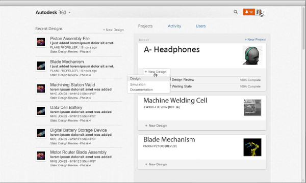
Still, CAD is only a part of Fusion 360. The program includes a dashboard, based on Autodesk 360, which tracks projects, designs, and revisions, and provides viewing, sharing collaboration, and activity tracking. The Fusion 360 client connects to the Autodesk 360 back-end through its integral web browser.
Cloud Integration
From a technical perspective, Fusion 360’s cloud integration makes possible things which would be much more difficult with a standalone CAD application.
As a start, with Fusion 360, you can work anywhere you have a reasonably good computer and internet connection. Because data is stored centrally, with revision management, there is no longer a problem with having multiple versions of a file spread out on multiple computers. (As an enthusiastic user of DropBox, I’ve gotten quite used to not needing to copy files back and forth between various computers at various locations.)
One of key design goals for Fusion 360 was that it be able work with the data that users have. That means reading and writing CAD files in a variety of formats. Normally, desktop CAD systems include a basic selection of import and export translators, of varying quality. If you want really good translators, you need to buy them separately. And they’re not cheap. With Fusion 360, the import/export translators are hosted on the cloud. As part of the package, you get high quality translators, for all the formats you’re likely to need. And you don’t have to worry about keeping them up to date.
Generally, any major capabilities in Fusion 360 that can be run on the cloud, are being run on the cloud. These include rendering, collaboration, viewing, and simulation. (To be fair, each one of these capabilities is substantive enough to warrant its own article.

Performance
Companies such as Autodesk love to talk about the “power” of the cloud. About “nearly infinite computing resources.” But there’s a big difference between having access to lots of computing resources, and being able to effectively use them.
With Fusion 360, the local client has been optimized to take advantage of parallelism in constraint solving, and geometric modeling. That’s not to say that, if you have an 8 core processor on your computer, Fusion is going to utilize all the power of all those cores. It’s merely to say that, in some cases, it will take advantage of multiple cores. If you happen to be doing an operation that’s not easy to parallelize (e.g., filleting all the edges on a single solid body), you shouldn’t expect to see much in the way of performance improvement from having multiple cores.
As a practical matter, Fusion 360 should be pretty fast in all client-based operations except for loading and saving files—which are constrained by the speed of your internet connection. However, in cloud-based operations, particularly rendering and simulation (which can take lots of advantage of parallelism), Fusion 360 should be more than just pretty fast.
Autodesk hasn’t tried to over-sell Fusion 360’s performance. If you’re doing mechanical designs with up to hundreds of parts, you’ll probably be happy with Fusion 360’s performance. If you’re doing designs with thousands of complex parts, for now you’ll probably want to look at Inventor, which has specific tools to optimize large assembly performance.
Licensing Terms
Despite all my best efforts, I haven’t been able to get a reading on the price range that Autodesk might charge for using Fusion 360. They’re just not saying. (Maybe because they’re still working it out.) Yet, reading between the lines, I believe that Autodesk isn’t going to try to squeeze every dollar out of Fusion 360 subscribers. More than likely, if you factor in advanced capabilities (e.g., translation, rendering, simulation, collaboration), the price will look pretty good, at least compared to the up-front cost of buying desktop software.
One of the critical issues with software as a service offerings, such as Fusion 360, is the terms and conditions under which they’re offered. I’ve looked at the terms and conditions for Autodesk 360, which should be similar to those for Fusion 360. While I don’t find them to be terrible, compared to other terms and conditions I’ve read, I do have some problems with them. First, there’s the question of which terms apply: those at the Autodesk legal notices page, or those on the Autodesk 360 landing page. (I assume it’s the former, but it’s not a good thing for it to be ambiguous.) Next, there’s the issue of limitation of liability. Autodesk completely disclaims any liability for any damages or loss.
While it’s understandable that Autodesk would want to disclaim all liability and have users waive all potential claims, that doesn’t make it a reasonable bargain for the consumer. It totally insulates Autodesk from any duty of care.
Given legitimate concerns regarding security, data loss, and service unavailablility, I can’t recommend using Fusion 360 for critical work until Autodesk publishes a service-level agreement—which I anticipate they may do when they get to the point of charging money for Fusion 360.
What’s missing
As previewed at Autodesk University, Fusion 360 is a capable CAD system, with impressive tools for interoperability, concept modeling, simulation, rendering, and collaboration. It’s crossed the threshold of being good enough for many uses cases. But it’s not a fully mature product. Pieces are missing.
Mobile. One significant missing piece is a mobile client. Particularly a client (or clients) to run on tablets. I suspect that this is not an oversight, but rather a decision, on the part of Autodesk, to move ahead while they sort-out the issue.
The existing client for Windows and Mac is pretty hefty, and requires quite a bit of memory and floating-point computational power, so it’s not a slam dunk to do a mobile version. Whether Autodesk chooses to implement native tablet clients, or to use virtualization, there is no doubt that they will offer a solution.
Off-line operation. This could be important. Only time will tell how and when Autodesk implements it.
API. There has been an application programming interface (API) for Fusion 360 all along. In fact, the Fusion 360 development team does their work using it—so it’s likely to be capable and stable. The interesting question will be how Autodesk chooses to expose the API, and make it available to users and third-party developers.
Parametrics. The current version of Fusion 360 allows the creation of precise feature-based solid models. But it doesn’t support parameterization of those models. Yet. This capability will certainly be added.
PMI. Fusion 360 would be a great tool to use in a model-based enterprise (MBE) workflow—if it supported Product and Manufacturing Information (PMI.) It’s not an oversight: The folks at Autodesk know that this is an important element in the future of CAD, so it’s going to be there in the future (after parametrics.)
Drawings. From what I’ve seen so far, Fusion 360 doesn’t support drawings yet. I wouldn’t be surpised to see them supported through an extension to AutoCAD WS.
Model Validation and Repar. In any workflow involving multiple 3D CAD formats, both model validation and model repair are practical requirements. (Yes, they’re very distinct and separate things.)
Large Assembly Performance. This is likely to be something that is tuned and optimized over time.
Concurrent Collaboration. Fusion 360 doesn’t appear to be designed for concurrent collaboration. But, it’s not hard for me to conceive of a way it could be added without needing to totally reinvent the product.
Specialty Workspaces. If you look at Autodesk Inventor, you’ll find that it supports a dizzying number of specialty applications, including sheet metal, electrical wiring, mold design, multibody dynamics, and on and on. These aren’t in Fusion 360 yet. But, given the example of Autodesk Labs Project Simulus, and Autodesk Simulation 360, you can expect that, over time, many of the capabilities that are now in Inventor will find their way into Fusion 360. Because Fusion 360 supports modular task-based workspaces, it wouldn’t be surprising to see them offered on a truly a la carte basis.
Hybrid/Private Cloud. Fusion 360 will run on Autodesk’s cloud. If you want to run it on your own private cloud, you may be out of luck. Unless you’re looking for 10,000 seats. Then, I’m guessing, Autodesk will work something out.
What about Inventor?
This is a delicate question. A few years ago, Dassault Systems previewed a cloud-based prototype of a future SolidWorks CAD product, and created a firestorm in the process, with some very vocal SolidWorks users becoming alarmed that this meant the end of the product they’d invested years to master. Autodesk has watched this from afar, and has no desire to repeat the experience themselves.
Fusion 360 does represent, in a very real way, the future of CAD for Autodesk. It has a clean software architecture, and is capable of being extended in ways that are not possible for Inventor. It’s not unreasonable to connect the dots, and come to the conclusion that Fusion 360 may be Inventor’s successor.
But Inventor is not going away anytime soon. Consider its position: It’s one of Autodesk’s hero products. With its large user base (many of which pay substantial annual subscription fees) It would be complete insanity for Autodesk to deprecate it.
While Autodesk has handled some product transitions poorly in the past (I’m thinking Mechanical Desktop and Architectural Desktop), they’ve also shown that they can manage portfolios with overlapping products (I’m thinking 3ds Max and Maya.) And they’ve also shown that they can maintain support for products over the long haul (I’m thinking AutoCAD.)
While at Autodesk University, I flat out asked Carl Bass about the issue of Inventor’s long term future. While he wasn’t willing to write anything in blood, he didn’t equivocate. He can easily see Inventor being an important CAD tool ten years in the future, and beyond. Though he’s a big proponent of the cloud, he recognizes that desktop applications will be with us for a very long time.
When can you get it?
You can sign up for beta now, at www.autodesk.com/fusion360. Commercial availability is slated for sometime next year.



 Maybe a little bit of background might help: Boulder is heavily populated with talented graphics programmers. For example, Sketchup (formerly owned by Google, and now owned by Trimble) and Spatial are both in the Boulder area. But they’re just the start. If Autodesk wanted to start a skunkworks development operation, Boulder would be an ideal place to locate it.
 For inexperienced designers, Simulation DFM provides quick feedback to help them avoid rookie mistakes. It’s sort of like an “idiot light” on a car’s dash, that warns you when something is wrong. And while old-hands might say they prefer gauges to idiot lights, experience has shown that idiot lights are useful to experts (even F1 drivers and fighter pilots) for catching their attention, and getting them to actually look at the gauges.